Electronics Fundamentals
Learn foundational electronics from the ground up: atomic electron flow, Ohm's law, AC vs DC waveforms, reading resistor color codes, capacitor charge storage, diode rectification, transistor switching, inductors, transformers, and 555 timer IC prototyping.
Electronics Fundamentals
Foundational electricity, atomic electron flow, Ohm's law, AC vs DC waveforms, resistors, capacitors, diodes, transistors, inductors, and 555 timer integrated circuits.
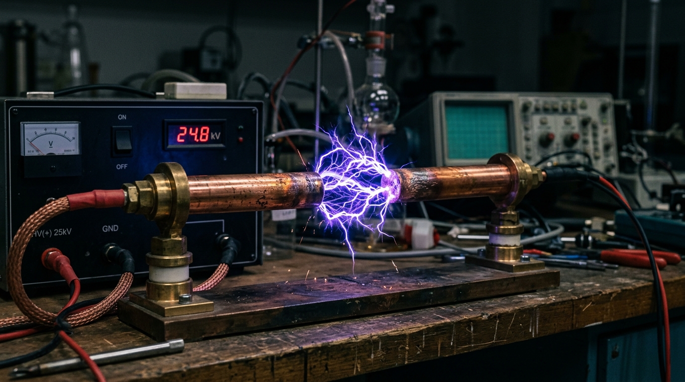
What is Electricity? Voltage, Current, Resistance & Ohm's Law Explained
Understand fundamental electricity from the atomic level: electron flow, voltage (potential difference), current (Amperes), resistance (Ohms), and the core Ohm’s Law relationship.
Electricity is the flow of negatively charged subatomic particles called electrons through a conductive material (copper, aluminum).
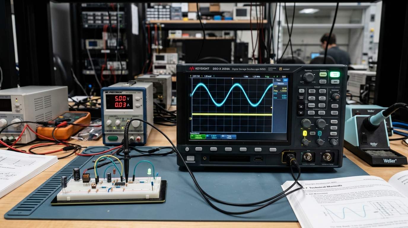
AC vs DC: Alternating Current vs Direct Current Explained
Compare Direct Current (DC) from batteries and microcontrollers with Alternating Current (AC) from wall outlets. Learn frequencies, RMS voltage, rectification, and transformers.
Direct Current (DC) flows in a single fixed direction with constant polarity; generated by batteries, solar panels, and DC power supplies.
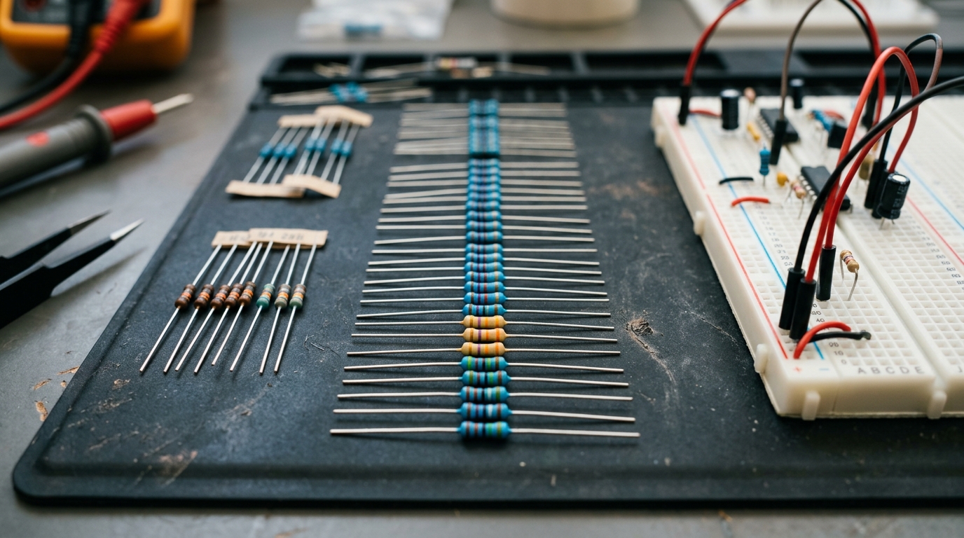
What is a Resistor? Working Principle, Color Code Bands & Series-Parallel Circuits
Master standard carbon film and metal film resistors: learn how to decode 4-band and 5-band color rings, calculate series/parallel combinations, and design voltage dividers.
Resistors limit current flow, drop voltage, and protect delicate components like LEDs and microcontrollers from burning out.
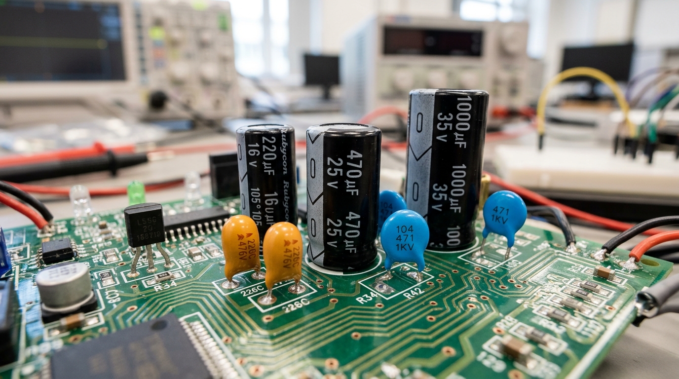
What is a Capacitor? Working, Dielectrics, Types & RC Filter Circuits
Learn how capacitors store electrical charge in electrostatic fields. Understand ceramic vs electrolytic polarity, Farad units, decoupling noise, and RC time constants.
A capacitor stores electrical energy in an electrostatic field between two conductive plates separated by an insulating dielectric material.
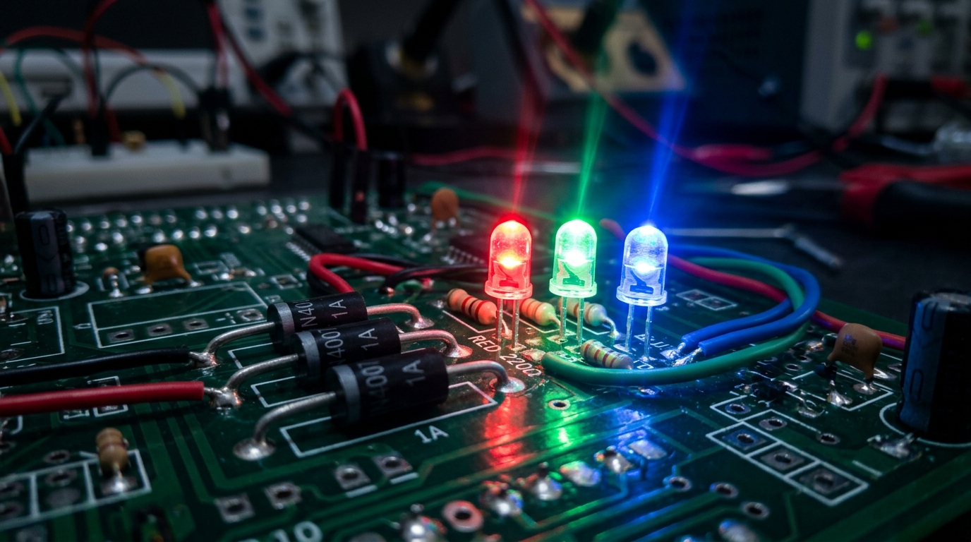
What is a Diode? PN Junction, Forward/Reverse Bias, LEDs & Rectification
Explore semiconductor PN junctions: learn how diodes act as one-way check valves for electricity, forward voltage drop (0.7V), LED colors, Zener clamping, and full-wave bridge rectifiers.
A diode allows electric current to flow in ONE direction only (Anode to Cathode) and blocks current in reverse.
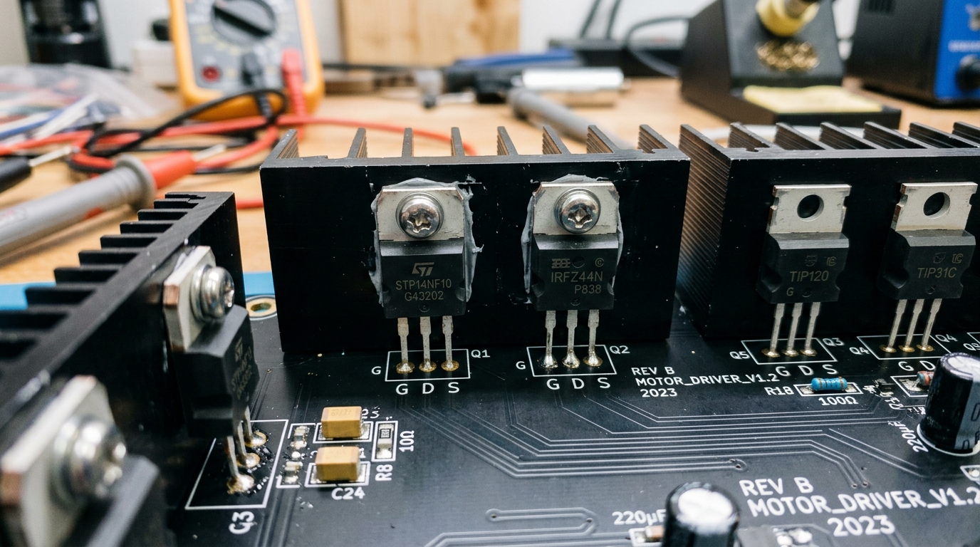
What is a Transistor? BJT (NPN/PNP) & MOSFETs as Electronic Switches
Discover the semiconductor revolution: understand Bipolar Junction Transistors (BJT NPN/PNP) vs Field-Effect Transistors (MOSFETs), saturation, cutoff, and driving motors.
A transistor is a 3-terminal semiconductor device that uses a tiny input signal to control a much larger output current.
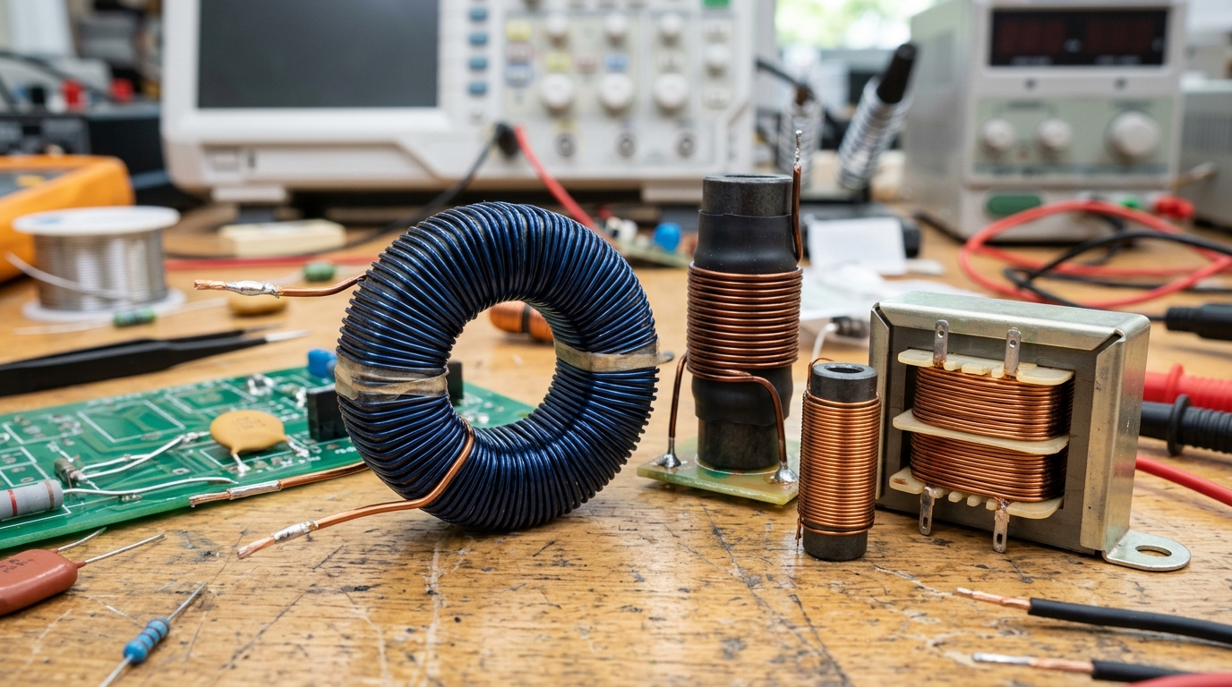
What is an Inductor? Magnetic Fields, Inductance, Back-EMF & Transformers
Explore electromagnetism in electronics: coils of wire, magnetic flux energy storage, Henrys, Back-EMF inductive kickback, and step-up/step-down transformers.
An inductor is a coil of insulated wire that stores energy in a magnetic field whenever current passes through it.
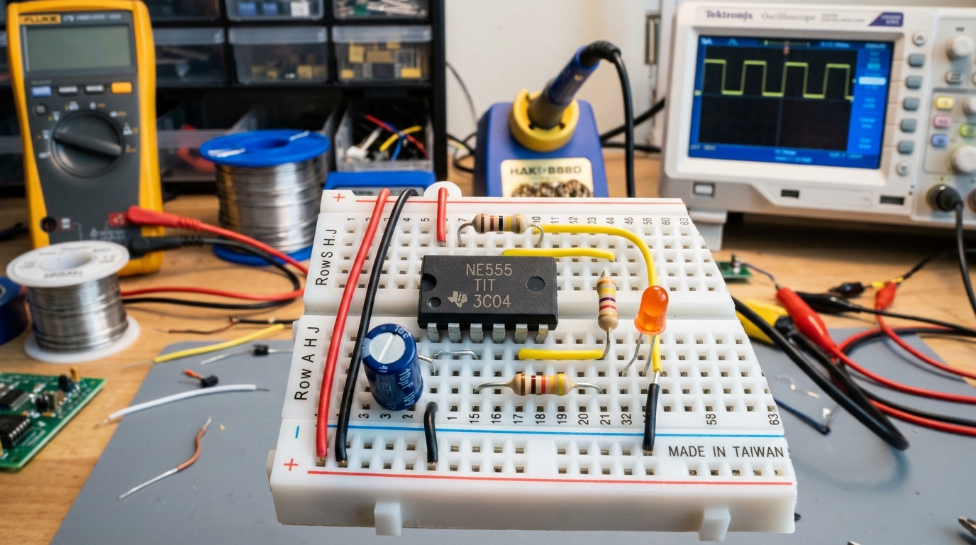
Integrated Circuits (ICs), 555 Timers, Breadboarding & Multimeter Guide
Put everything together: understand Integrated Circuits (ICs), build classic 555 timer pulse circuits, master solderless breadboards, and measure circuits with a digital multimeter.
An Integrated Circuit (IC) bundles hundreds to billions of microscopic transistors, diodes, and resistors onto a single monolithic silicon wafer.
Bench & Workflow Essentials
Master your lab workbench: proper breadboard rail layout, reading schematics & symbols, multimeter diagnostic probing, DC bench power supply CV/CC modes, and wire crimping.
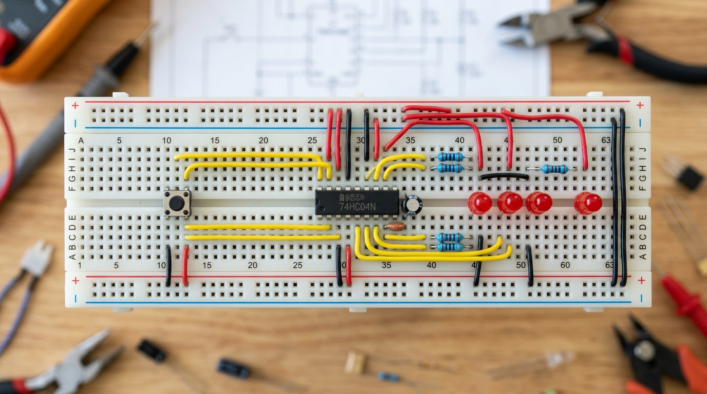
Using a Breadboard Properly: Rails, Layout & Common Mistakes
Master solderless breadboard prototyping: understand split power rails, internal spring contact clips, IC placement across center troughs, color-coded wiring rules, and how to avoid erratic loose connections.
Each 5-hole terminal strip in the breadboard body connects horizontally across letters A-E and F-J.
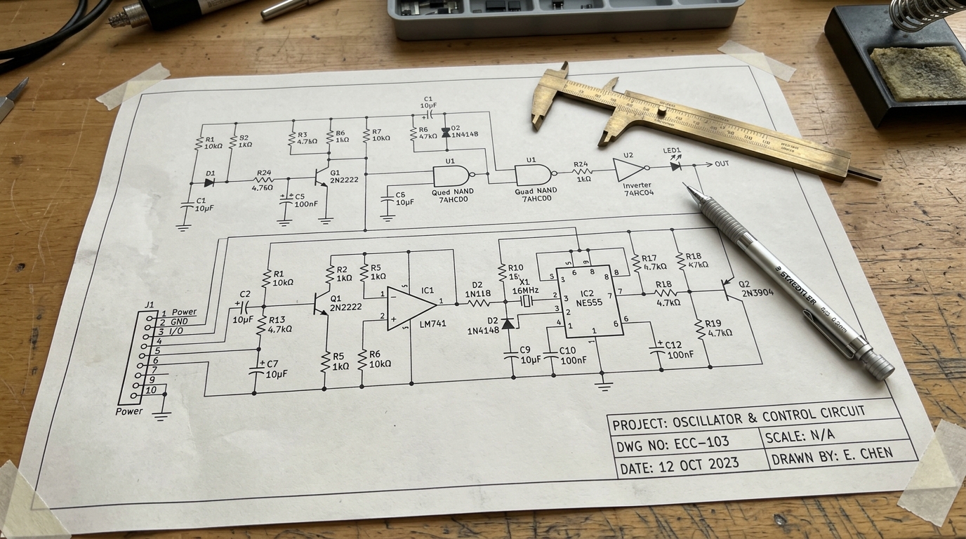
Reading Circuit Schematics & Electronic Component Symbols
Demystify circuit diagrams: learn American vs European schematic symbols, power rails, junction dots, polarized components, net labels, and how to translate schematics into real hardware.
A schematic diagram represents electrical connections logically, not physical component locations on a board.
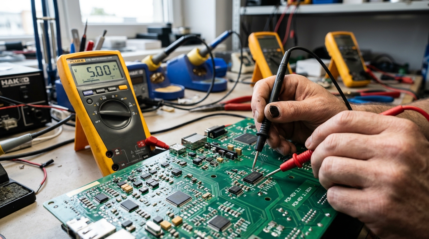
Using a Multimeter: Hands-On Guide (Voltage, Continuity, Shorts)
Practical step-by-step guide to digital multimeters: probing DC voltages, continuity beeper tracing, detecting unintended ground shorts, measuring resistance, and measuring current safely.
The Black probe ALWAYS plugs into the COM (Common/Ground) port.
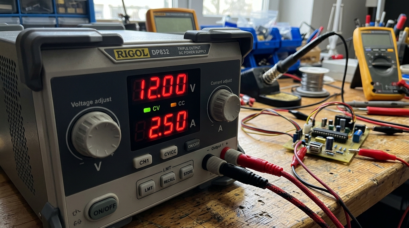
Bench Power Supply Basics: Constant Voltage (CV) & Constant Current (CC)
Master the laboratory DC bench power supply: set exact voltage rails, use Constant Current (CC) mode as an electronic fuse to save prototype boards from burning, and calculate load power.
A bench power supply provides adjustable, regulated DC voltage (0-30V) and current (0-5A/10A) with real-time digital readouts.
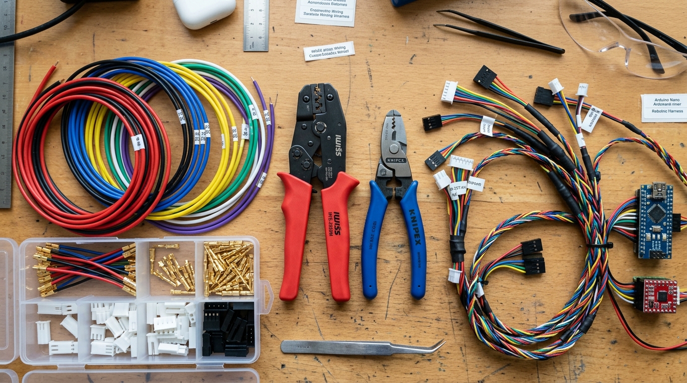
Wire Gauges (AWG), Connectors & Crimping Guide for Robotics
Complete wiring guide: decode American Wire Gauge (AWG) current ratings, master robotics connectors (JST, DuPont, XT30, XT60, Molex), and crimp reliable locking terminals with ratchet crimpers.
In American Wire Gauge (AWG), smaller numbers represent THICKER wire with higher current-carrying capacity.
Soldering & Permanent Builds
Transform breadboard prototypes into permanent robotics hardware: through-hole soldering, desoldering rework, perfboard wiring, and designing custom KiCad PCBs for JLCPCB.

Through-Hole Soldering for Beginners: Tools, Heat Control & Safety
Learn hands-on through-hole soldering from scratch: soldering iron selection, temperature control (300°C–350°C), leaded vs lead-free solder, flux activation, making shiny concave fillets, and avoiding cold joints.
Soldering is not gluing: it creates a molecular-level intermetallic bond between the copper pad and component lead.

Desoldering Techniques & Tools: Wick, Pumps & Rework
Master error correction and component harvesting: use copper desoldering braid (wick), manual spring-loaded vacuum pumps (solder suckers), and hot air rework stations safely.
Adding fresh solder and flux to an old joint makes desoldering MUCH easier by restoring heat transfer and lowering oxide barriers.

Working with Perfboard & Protoboard: Layouts & Wiring
Step beyond breadboards: master pad-per-hole perfboard and stripboard layouts, point-to-point bus wire routing, solder bridging techniques, and building rugged DIY sensor shields.
Double-sided plated-through-hole (PTH) FR4 fiberglass perfboard is far superior to cheap single-sided phenolic paper boards.
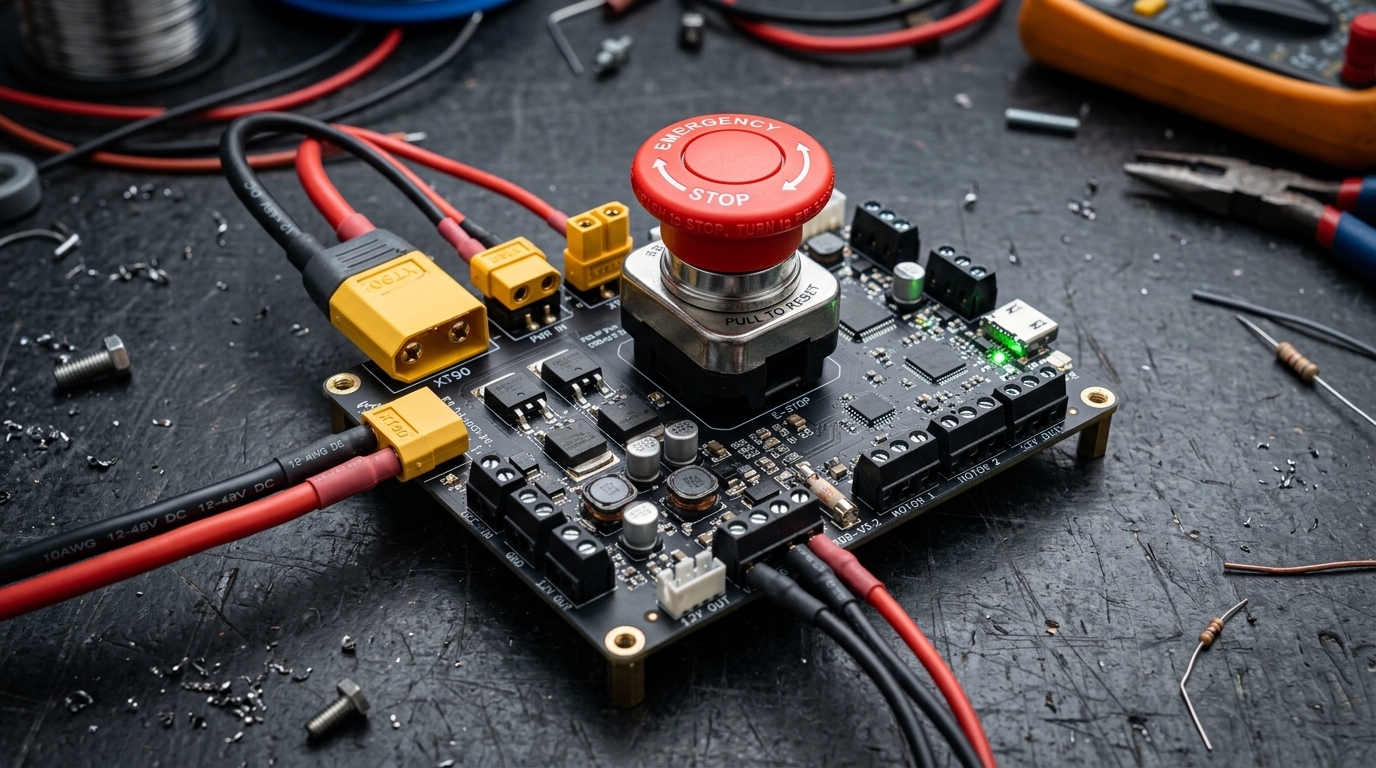
From Breadboard to Permanent Build: Prototyping Blueprint
The complete engineering roadmap: test and validate circuits on solderless breadboards, document schematics, design durable perfboard or custom PCB modules, and package electronics in robotic enclosures.
Never move directly from a theoretical idea to a soldered board; always validate current draw and logic on a breadboard first.
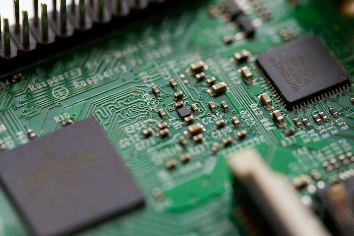
Intro to Custom PCBs: KiCad & EasyEDA to JLCPCB Fabrication
Design professional printed circuit boards: create schematics in KiCad/EasyEDA, assign footprints, route traces and ground copper pours, run Design Rule Checks (DRC), and generate Gerber files for fab houses.
Custom 2-layer PCBs cost as little as $2 for 5 boards and eliminate 99% of hand-wiring mistakes.
Circuit Fundamentals — Hands-On
Practical circuit mechanics: series vs parallel multimeter measurements, voltage dividers, verifying Kirchhoff's laws (KVL/KCL), pull-up/pull-down resistors, debouncing, and PWM.
Series vs Parallel Circuits (with Real Multimeter Measurements)
Hands-on lab guide: calculate, wire, and measure series vs parallel resistor and LED networks using a digital multimeter. Understand equivalent resistance, current splitting, and voltage drops.
In Series: Current is identical through all components (I_total = I_1 = I_2); Voltages add up (V_total = V_1 + V_2).

Voltage Dividers Explained & Built: Formula, Sensor Interfacing & Loading
Master the fundamental circuit of analog electronics: derive the voltage divider formula, build sensor interfaces for photoresistors and thermistors, and solve the output impedance loading effect.
A voltage divider produces an output voltage proportional to the ratio of two resistors: V_out = V_in · R_2 / (R_1 + R_2).

Kirchhoff's Laws (KVL & KCL): Practical Multimeter Verification
Demystify Kirchhoff’s Voltage Law (KVL) and Kirchhoff’s Current Law (KCL): explore node and loop analysis with hands-on breadboard circuit verification using a digital multimeter.
Kirchhoff’s Current Law (KCL): The sum of currents entering any circuit node equals the sum of currents leaving: Sum of I_in = Sum of I_out.
Pull-Up vs Pull-Down Resistors: Floating Pins & Button Circuits
Eliminate erratic digital glitches: learn why uncommitted microcontroller inputs float into high-impedance chaos, calculate 10kΩ pull-up vs pull-down circuits, and configure internal MCU pull-ups in code.
Microcontroller input pins have massive internal input impedance (>100MΩ); when disconnected, they act like radio antennas picking up electromagnetic noise and oscillating wildly.

Switch Debouncing Explained: RC Hardware Filters & Software Algorithms
Solve phantom multiple button clicks: understand mechanical contact bounce physics, build analog RC low-pass debounce hardware filters, and write non-blocking millis() software debouncers.
When mechanical switch contacts collide, elastic metallic spring leaves bounce rapidly for 2ms–10ms before settling.
Introduction to PWM (Pulse Width Modulation): Duty Cycle & Motor Speed
Control power digitally: master Pulse Width Modulation (PWM), calculate duty cycle percentages, understand switching frequencies, dim LEDs smoothly, and control DC motor speed and servo angles.
Pulse Width Modulation (PWM) rapidly toggles a digital signal between full ON and full OFF to simulate a variable analog voltage.
Essential Building Blocks
Core hardware primitives: switches, electromechanical relays, potentiometers, resistive sensors (LDR, NTC thermistors, trimpots), voltage regulators, and op-amp comparators.

Switches, Relays & Buttons: Mechanical Switching & Coil Isolation
Master electromechanical switching: understand SPST, SPDT, and DPDT switch topologies, relay coil electromagnetic actuation, optical galvanic isolation, and flyback diode snubbers.
Poles (P) define how many separate circuits a switch controls; Throws (T) define how many output positions each pole connects to.

Potentiometers Explained: 3-Pin Wiring, Tapers & Analog Control
Master rotary and slide potentiometers: decode 3-pin wiring, compare linear (B) vs logarithmic (A) tapers, interface dials with microcontroller ADC pins, and wire variable rheostats.
A potentiometer is an adjustable voltage divider constructed with a curved resistive carbon track and a sliding wiper contact.

LDR, Thermistor & Trimpots: Resistive Sensors & Calibration
Convert the physical world into electrical signals: explore Light Dependent Resistors (LDR), Negative Temperature Coefficient (NTC) thermistors, Steinhart-Hart temperature math, and multi-turn precision trimpots.
LDR photoresistors drop in electrical resistance when photon energy excites electrons across the cadmium sulfide (CdS) bandgap.

Voltage Regulators for Beginners: Linear 7805 vs Buck & Boost Converters
Power your robotics electronics cleanly: compare linear regulators (LM7805, AMS1117) with high-efficiency switching DC-DC Buck (step-down) and Boost (step-up) converters.
Microcontrollers require exact voltages (+5.0V or +3.3V); unregulated battery packs fluctuate continuously as they discharge.

Op-Amp as a Comparator: Threshold Detection & Hysteresis
Make analog decisions: master Operational Amplifiers (Op-Amps) and dedicated comparators (LM393, LM358), threshold voltage references, open-collector outputs, and Schmitt trigger hysteresis.
A Voltage Comparator compares two input voltages (V_+ and V_-) and outputs a digital HIGH or LOW based on which is larger.
Digital Logic Basics
The foundation of microprocessors: binary number systems, TTL vs CMOS voltage levels, transistor logic gates (AND, OR, NOT, NAND, NOR, XOR), and truth table Boolean algebra.

Understanding Binary Numbers & Digital Logic Levels (TTL vs CMOS)
Master the language of computers and robotics: understand base-2 binary counting, hex representations, bytes/nibbles, and voltage threshold logic standards (5V TTL, 3.3V CMOS, 1.8V Low Voltage).
Digital electronics use Base-2 (Binary) because transistors act most reliably as binary switches (Fully ON = 1, Fully OFF = 0).

Logic Gates Explained: AND, OR, NOT, NAND, NOR & XOR Transistor Circuits
Explore the building blocks of microprocessors: understand AND, OR, NOT, NAND, NOR, and XOR logic gates, build transistor logic circuits on breadboards, and master universal NAND logic.
Logic gates are electronic circuits that perform elementary Boolean operations on one or more binary inputs to produce a single output.

Truth Tables & Boolean Algebra: Combinational Logic Design
Design digital logic circuits systematically: construct multi-input truth tables, master Boolean algebra laws (De Morgan’s Laws, Distributive, Absorption), and simplify gate counts using Karnaugh Maps.
A Truth Table lists every possible combination of binary inputs (for n inputs, there are 2^n rows) and the resulting output.
Survival Skills for Beginners
Essential engineering survival instincts: decoding component datasheets, project power delivery (USB-C PD, barrel jacks), ESD & LiPo safety, diagnostic debugging flowcharts, and top mistakes.

How to Read an Electronic Component Datasheet: The Survival Guide
Extract critical engineering parameters from 50-page datasheets: decode Absolute Maximum Ratings, pinouts, electrical characteristics (typical vs max), timing diagrams, and typical application schematics.
A datasheet is the legal manufacturer contract specifying the exact physical, electrical, and thermal boundaries of a component.
Powering Your Projects: USB-C PD, Wall Adapters & Battery Packs
Clean, reliable power delivery for robots: compare USB 5V, USB-C Power Delivery (PD) triggers, DC barrel jack wall adapters, center-positive polarity, and multi-cell battery holders.
Standard USB 2.0/3.0 ports output 5.0V regulated DC capped at 500mA–1.5A; modern USB-C Power Delivery (PD) can negotiate 9V, 12V, 15V, or 20V at up to 5A (100W).

ESD Electrostatic Discharge & LiPo Battery Safety for Robotics
Protect components and your workshop: prevent Electrostatic Discharge (ESD) damage on sensitive CMOS chips, master Lithium Polymer (LiPo/Li-ion) charging protocols, C-ratings, balance charging, and fire prevention.
Walking across a carpet generates up to 15,000V of static electricity; a 100V discharge can punch microscopic holes through delicate MOSFET gate oxides.

"My Circuit Is Dead": Step-by-Step Electronics Troubleshooting Flowchart
The universal hardware debugging methodology: follow a proven step-by-step diagnostic checklist to find power rail shorts, cold solder joints, reversed diodes, floating reset pins, and blown regulators.
80% of all non-functioning prototype circuits fail due to simple power and ground wiring errors.

Top 10 Common Beginner Mistakes in Electronics & How to Avoid Them
Avoid costly hardware magic smoke: review the top 10 most frequent mistakes beginner robotics builders make, from omitted current-limiting resistors to missing common grounds and floating reset pins.
Mistake #1: Forgetting to connect all separate battery and supply grounds together into a Common Ground.
Voltage, Current & Resistance Explained
Intuitive deep dives into electrical physics: the hydraulic water pipe analogy, resistor color codes, capacitor motor noise snubbers, diode polarity & flyback, and power MOSFET switching.

The Water Pipe Analogy: An Intuitive Guide to Voltage, Current & Resistance
Visualize invisible electricity intuitively: understand voltage as hydraulic pressure, current as gallons per second flow rate, resistance as pipe diameter constriction, and Ohm’s Law balance.
Voltage (Volts) is electrical pressure: a higher elevated water tank creates higher pressure to push water down pipes.

Resistors in Practice: Color Codes & Pull-Up/Pull-Down Usage
Hands-on resistor mastery: decode 4-band and 5-band color rings effortlessly, select E12 standard preferred values, calculate power dissipation (I²R), and implement pull-up/pull-down networks.
Color codes use standardized colors: Black(0), Brown(1), Red(2), Orange(3), Yellow(4), Green(5), Blue(6), Violet(7), Gray(8), White(9).

Capacitors: Filtering Motor Noise & Smoothing Power Rails
Protect robotics computers from high-power motor interference: understand bulk electrolytic power smoothing, high-frequency ceramic decoupling bypass, and motor brush EMI snubber networks.
Brushed DC motors and servo motors generate massive high-frequency electrical noise and voltage dips on power rails.
Diodes & LEDs: Forward Voltage, Polarity & Flyback Protection
Master semiconductor diodes: decode forward voltage drop (Vf), polarity orientation, size LED current-limiting resistors, and implement reverse-polarity and inductive flyback snubber protection.
A diode allows current in one direction (Anode to Cathode); the silver painted stripe marks the Cathode (Negative terminal).

Transistors & MOSFETs: Switching Heavy Loads with Small MCU Signals
Control high-power actuators: compare current-controlled BJTs (2N2222) with voltage-controlled N-Channel MOSFETs (IRLZ44N, AO3400), gate thresholds, Rds(on) resistance, and gate driver circuits.
Microcontroller GPIO pins are limited to 20mA; transistors allow 3.3V/5V logic to switch 50A+ high-power loads.
Power Sources for Robotics
Power systems engineered for robots: comparing battery chemistries (9V, AA NiMH, 18650 Li-ion, LiPo), why 9V batteries fail for motors, and switching DC-DC buck/boost regulators.
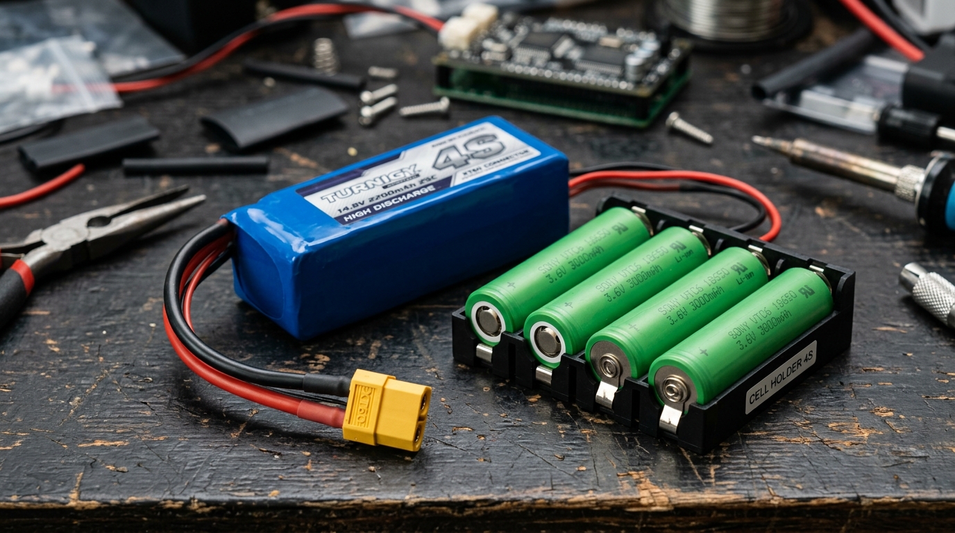
Battery Types Compared for Robotics: 9V, AA, 18650 Li-ion & LiPo Packs
Select the optimal battery for your robot: compare energy densities, internal resistance, continuous C-discharge ratings, cell chemistries (Alkaline, NiMH, LiFePO4, Li-ion, LiPo), and runtime calculations.
A battery must satisfy two distinct requirements: total energy capacity (milliamp-hours, mAh) AND peak burst current capability (Amps).
Why 9V Rectangular Block Batteries Fail for Robotics Motors
The #1 beginner trap revealed: understand the high internal resistance (1–3Ω) of 9V PP3 alkaline batteries, catastrophic voltage sag under motor inrush current, and superior multi-cell alternatives.
Standard 9V block batteries (PP3) were designed for ultra-low-drain smoke alarms (10µA–50mA), NOT high-current robotics motors.
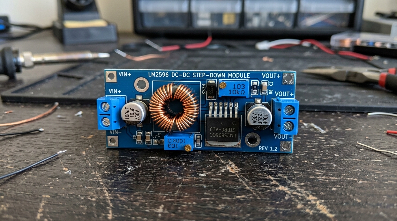
Voltage Regulators & Buck/Boost DC-DC Converters: Complete Selection Guide
Architect optimal power rails: compare LM7805/AMS1117 linear regulators with high-efficiency switching Buck (step-down), Boost (step-up), and Buck-Boost DC-DC modules for robotics.
Linear Regulators (LM7805) provide ultra-clean low-noise power for sensitive analog sensors, but waste energy as heat when V_in - V_out is large.
Core Bench Skills Recap
Quick-reference master summaries: breadboard clip architecture, multimeter 101 diagnostic workflows, and soldering temperature control, flux, and workshop safety essentials.

Breadboard Mastery: Internal Rail Layout & Clean Wiring Architecture
Comprehensive recap of rapid prototyping: master solderless breadboard internal nickel spring clips, power distribution bus bridges, flush lead routing, and fatal connection traps.
Each 5-hole terminal row connects horizontally with spring tension; DIP IC chips straddle the 0.3-inch center trough.

Multimeter 101: DC Voltage, Continuity & Tracing Shorts
Core measurement recap: master probe jack configurations, measure DC rail voltages, trace PCB broken tracks with the continuity beeper, and check diode forward voltage drops safely.
Black probe always stays in the COM jack; Red probe goes in the V/Ω/mA jack for 95% of measurements.

Soldering & Desoldering: Temperature Control, Flux & Workshop Safety
Core hardware assembly recap: master soldering iron heat control (300°C–350°C), flux chemical action, brass sponge tip tinning, desoldering pumps, copper wick extraction, and fume safety.
Heat both the component lead AND the copper pad simultaneously for 2 seconds before applying solder.