Key Engineering Takeaways
- •Electricity is the flow of negatively charged subatomic particles called electrons through a conductive material (copper, aluminum).
- •Voltage (V in Volts) is the electrical pressure or potential difference pushing charges between two points.
- •Current (I in Amperes) is the rate of electron flow (1 Ampere = 1 Coulomb of charge per second = 6.242 × 10¹⁸ electrons/sec).
- •Resistance (R in Ohms Ω) is the opposition a material offers to the passage of electric current.
- •Ohm's Law (V = I · R) and Power (P = V · I = I² · R) form the bedrock foundation of all electronic design.
- • Basic arithmetic (multiplication and division)
- • Digital Multimeter
- • 9V or 5V DC Power Source
- • Breadboard
- • Assorted Resistors (330Ω, 1kΩ, 10kΩ)
- • LEDs
What is Electricity? Atoms & Free Electrons
At the most fundamental level, all physical matter is constructed of atoms. Each atom contains a dense central nucleus composed of positively charged protons and neutral neutrons, surrounded by orbiting shells of negatively charged electrons.
In electrical conductors (such as copper wire, silver, and aluminum), the electrons in the outermost orbital shell (valence electrons) are loosely bound to their parent nuclei. When an external energy force is applied, these valence electrons detach and drift freely from atom to atom.
This directional, synchronized movement of free charge carriers through a conductive medium is what we define as electric current.
Voltage, Current & Resistance: The Water Pipe Analogy
To visualize electricity intuitively without needing to see invisible microscopic electrons, engineers use the classic Water Pipe Analogy:
- 1Voltage (V, Volts): Think of this as water pressure from an elevated tank or water pump. The higher the tank or stronger the pump, the harder the water is pushed through the pipe. Voltage is the electrical "push" between two points.
- 2Current (I, Amperes / Amps): This is the actual volume flow rate of electrons moving through the wire (like gallons per minute flowing out of a hose). 1 Ampere means over 6 quintillion electrons are flowing past every second!
- 3Resistance (R, Ohms / Ω): Think of this as a narrow restriction or valve in the pipe that squeezes down and restricts how easily water can flow. A high resistance limits current to a tiny trickle.
Conventional Current vs Actual Electron Flow
A historical quirk every beginner encounters is the direction of electric current:
- Conventional Current Flow: In the 1700s, Benjamin Franklin guessed that positive charges flowed from the Positive (+) terminal to the Negative (-) terminal. Circuit schematics, diode arrows, and transistor symbols still point in this direction today!
- Actual Electron Flow: Modern physics proved that negatively charged electrons actually travel from Negative to Positive (- to +).
In practical circuit design and debugging, engineers universally follow Conventional Current (Positive to Negative).

Ohm's Law: Mathematical Relationships & Triangle
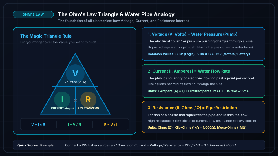
Discovered by Georg Simon Ohm in 1827, Ohm's Law is the most important formula in all electronics. It proves that Voltage, Current, and Resistance are locked together in a direct relationship:
The 3 Easy Formulas:
- Voltage = Current × Resistance (V = I × R)
- Current = Voltage / Resistance (I = V / R)
- Resistance = Voltage / Current (R = V / I)
Simple Worked Example:
If you connect a 12V battery across a 24Ω resistor:
- Current = 12V / 24Ω = 0.5 Amperes (500mA)
# Python script to calculate Voltage, Current, or Resistance
def ohms_law(v=None, i=None, r=None):
    if v is None and i is not None and r is not None:
        return i * r  # Voltage in Volts
    elif i is None and v is not None and r is not None:
        return v / r  # Current in Amperes
    elif r is None and v is not None and i is not None:
        return v / i  # Resistance in Ohms
    else:
        raise ValueError("Provide exactly two variables to solve for the third.")

# Example: 5V supply across 220 Ohm resistor
current_amps = ohms_law(v=5.0, r=220.0)
print(f"Current flowing: {current_amps * 1000:.2f} mA")
Electrical Power: Calculating Watts (P = V · I)
Electrical Power (P), measured in Watts (W), is the rate at which electrical energy does real work (or generates heat):
The Power Formulas:
- Power (Watts) = Voltage (V) × Current (I)
- Power (Watts) = Current² × Resistance
Simple Example:
If a robotics circuit draws 2 Amps at 5 Volts:
- Power = 5V × 2A = 10 Watts
Always check that your resistors, motor drivers, and transistors are rated for the wattage they produce, or they will overheat and burn out!
Frequently Asked Questions
What is the difference between Voltage and Current?
Voltage is the electrical pressure (potential energy difference) between two points, while Current is the actual rate of physical charge moving through the wire. You can have voltage without current (like an unplugged battery), but you cannot have current without voltage pushing it.
What causes electrical resistance?
As electrons move through a material, they collide with atoms and crystal lattice impurities in the conductor. These collisions convert kinetic electrical energy into thermal heat energy, resisting current flow.