Key Engineering Takeaways
- •Resistors limit current flow, drop voltage, and protect delicate components like LEDs and microcontrollers from burning out.
- •Resistor values are color-coded with standardized bands (Black=0, Brown=1, Red=2, Orange=3, Yellow=4, Green=5, Blue=6, Violet=7, Gray=8, White=9).
- •Resistors in Series add together: R_total = R1 + R2 + R3.
- •Resistors in Parallel reduce total resistance: 1/R_total = 1/R1 + 1/R2 (Total resistance is always lower than the smallest resistor).
- •A Voltage Divider (V_out = V_in · R2 / (R1 + R2)) is the fundamental circuit for analog sensors (LDRs, thermistors, potentiometers).
- • Ohm's Law basics (V = I · R)
- • Assorted Resistor Kit (100Ω to 1MΩ)
- • 10kΩ Potentiometer
- • Digital Multimeter
- • Breadboard
What is a Resistor & How Does It Work?
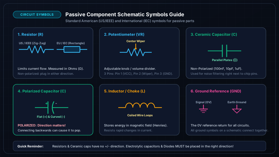
A Resistor is a passive two-terminal electronic component that implements electrical resistance as a circuit element.
Constructed from a ceramic rod coated with a thin film of carbon or metal alloy, the resistor deliberately impedes the flow of electrons, converting excess electrical energy into safe thermal dissipation.
Core Functions of Resistors:
- 1Current Limiting: Preventing LEDs and microcontroller pins from drawing destructive currents.
- 2Voltage Division: Stepping down high voltages to measurable levels for ADC inputs.
- 3Pull-Up & Pull-Down: Ensuring digital input pins never float in an undefined noisy state.
- 4Timing Circuits: Establishing RC delay times with capacitors.

How to Read 4-Band & 5-Band Resistor Color Codes
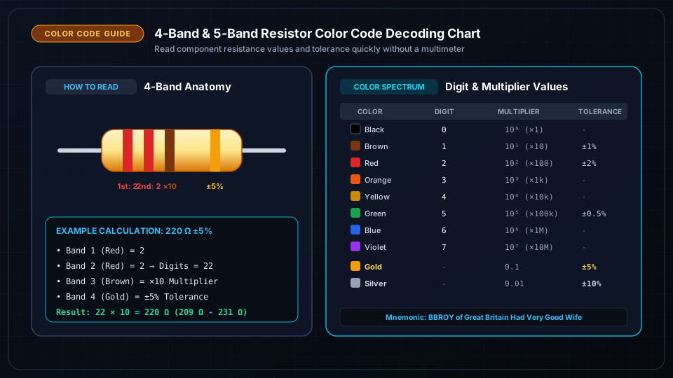
Because through-hole resistors are tiny, printed text would rub off. Instead, standardized colored rings encode the resistance value in Ohms (Ω) and tolerance:
The Universal Color Code Table:
| Color | Digit Value | Multiplier | Tolerance |
|---|---|---|---|
| Black | 0 | × 10^0 (1 Ω) | — |
| Brown | 1 | × 10^1 (10 Ω) | ± 1% |
| Red | 2 | × 10^2 (100 Ω) | ± 2% |
| Orange | 3 | × 10^3 (1 kΩ) | — |
| Yellow | 4 | × 10^4 (10 kΩ) | — |
| Green | 5 | × 10^5 (100 kΩ) | ± 0.5% |
| Blue | 6 | × 10^6 (1 MΩ) | ± 0.25% |
| Violet | 7 | × 10^7 (10 MΩ) | ± 0.1% |
| Gray | 8 | × 10^8 | — |
| White | 9 | × 10^9 | — |
| Gold | — | × 0.1 | ± 5% |
| Silver | — | × 0.01 | ± 10% |
Example: Reading a 4-Band Resistor (Brown - Black - Red - Gold)
- 11st Band (Brown) = 1
- 22nd Band (Black) = 0 to Digits: 10
- 33rd Band (Red Multiplier) = × 100
- 44th Band (Gold Tolerance) = ± 5%
Resistors in Series vs Parallel: Complete Math
1. Resistors in Series
When resistors are connected end-to-end along a single path, current must pass through each one sequentially. The same current flows through all, and resistances simply add together:
Example: 220 Ω + 470 Ω + 1000 Ω = 1690 Ω = 1.69 kΩ.
---
2. Resistors in Parallel
When resistors are connected side-by-side across the same two voltage nodes, current divides among branches. The total equivalent resistance drops:
For two resistors in parallel:
Example: Two 100 Ω resistors in parallel give:
Designing Voltage Divider Sensor Circuits
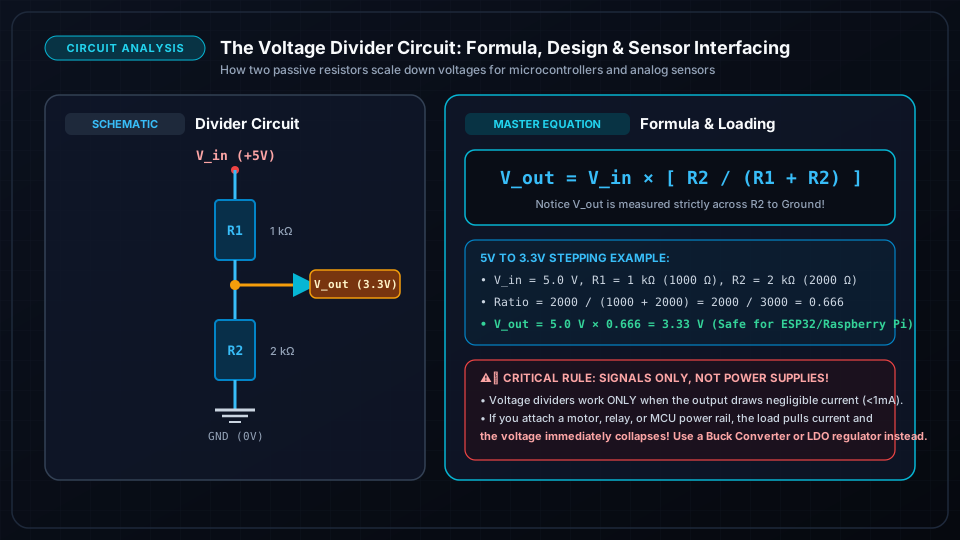
A Voltage Divider produces an output voltage that is a fraction of its input voltage:
If R_1 is a Light Dependent Resistor (LDR photoresistor) whose resistance changes from 500 Ω (bright light) to 100 kΩ (darkness), and R_2 = 10 kΩ:
- In Bright Light: V_out = 5V × (10k / 0.5k + 10k) ≈ 4.76V
- In Darkness: V_out = 5V × (10k / 100k + 10k) ≈ 0.45V
This changing voltage is fed directly into an Arduino or ESP32 Analog-to-Digital Converter (ADC) pin to detect room brightness!
Frequently Asked Questions
Does resistor orientation matter when inserting into a breadboard?
No! Resistors are non-polarized components. You can connect them in either direction in a circuit without affecting performance.
What happens if a resistor gets too hot?
If the power dissipated (P = I² · R) exceeds its wattage rating (e.g. 0.25W), the resistor body will scorch, change its resistance value permanently, or burn open like a fuse.