Key Engineering Takeaways
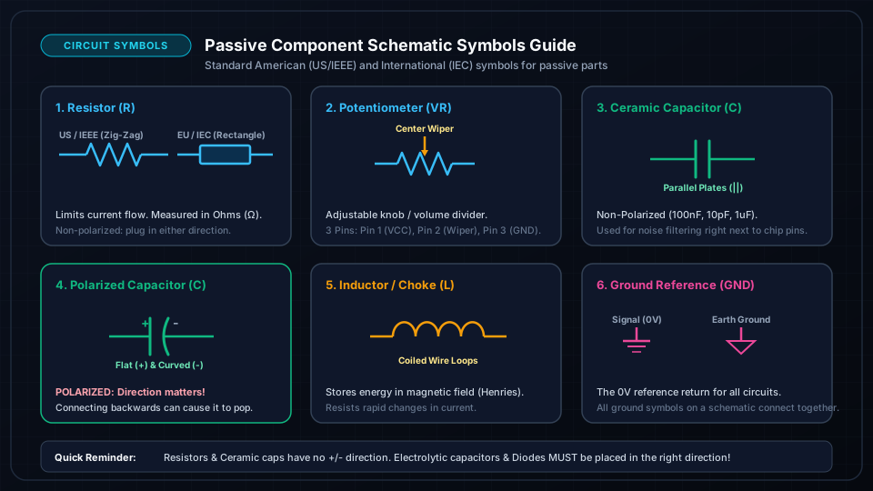
- •An inductor is a coil of insulated wire that stores energy in a magnetic field whenever current passes through it.
- •Inductance (L) is measured in Henrys (H), millihenrys (mH), and microhenrys (µH).
- •Lenz's Law: Inductors resist any change in current. When current starts, inductors oppose the increase; when current stops, they create a high-voltage spike (Back-EMF) to keep current flowing.
- •Transformers transfer AC electrical energy between two isolated coils via mutual magnetic induction: Vp/Vs = Np/Ns.
- •Inductors are the vital active components in high-efficiency DC-DC Buck and Boost switching power regulators.
- • Magnetic fields and AC/DC basics
- • Toroid / Drum Core Inductor (100µH - 10mH)
- • Step-Down Mains Transformer
- • Multimeter
What is an Inductor & Electromagnetic Induction
When electric current passes through any conductor, it generates a concentric magnetic field around the wire.
By coiling the wire tightly into loops (often around an iron, ferrite, or air core), the magnetic field lines concentrate into a powerful unified magnetic flux. This component is called an Inductor (or Choke / Coil).
Unlike a capacitor (which stores energy in an electrostatic field and opposes changes in voltage), an inductor stores energy in a magnetic field and opposes changes in current.
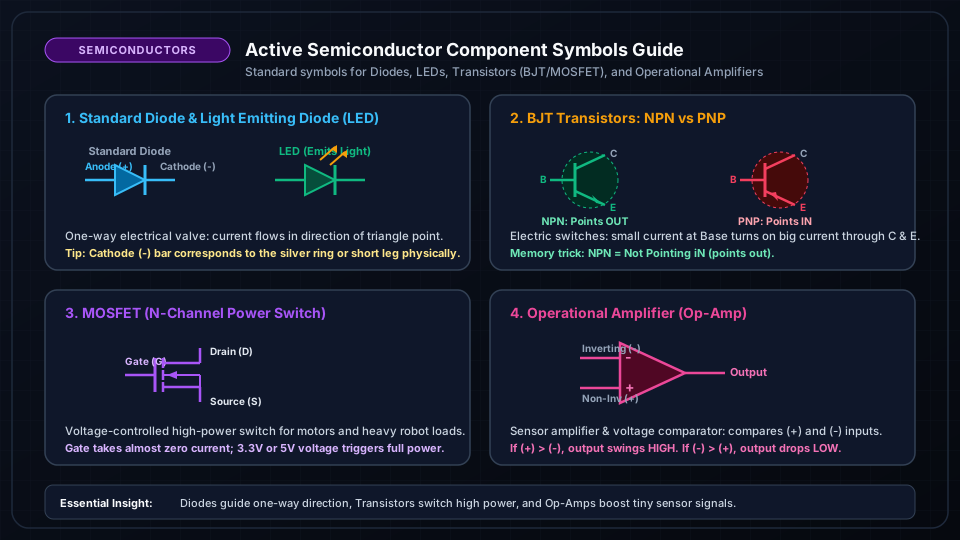
Lenz's Law & Back-EMF Voltage Spikes
According to Faraday's Law of Induction and Lenz's Law, when current flowing through an inductor changes, the collapsing or expanding magnetic field induces a counter-voltage:
If you have a 12V DC motor or relay drawing 1A and you suddenly open the switch in 1µs (dt = 10^-6s):
This massive instantaneous Back-EMF spike will produce a visible blue electrical spark across mechanical switches or vaporize driving transistors unless snubbed with a diode.

How Transformers Work: Step-Up & Step-Down Winding Ratios
A Transformer places two independent inductor coils (Primary and Secondary) around a shared iron core.
When AC current flows through the primary coil, its alternating magnetic flux couples through the core and induces an AC voltage in the secondary coil:
- Step-Down Transformer: N_p = 1000 turns, N_s = 100 turns to Steps 230V AC down to 23V AC.
- Step-Up Transformer: More secondary turns to Boosts voltage higher.
Frequently Asked Questions
Do inductors work with DC current?
For constant steady-state DC, once the magnetic field stabilizes, an inductor acts like a simple piece of copper wire (near-zero resistance). It only exhibits inductive reactance when current is turning on, turning off, or oscillating (AC/PWM).