Key Engineering Takeaways
- •An Integrated Circuit (IC) bundles hundreds to billions of microscopic transistors, diodes, and resistors onto a single monolithic silicon wafer.
- •Pin 1 is always located to the LEFT of the top half-moon notch or identified by a small circular dimple dot.
- •The 555 Timer is the most famous IC in history, capable of operating as an Astable oscillator or Monostable timer.
- •Solderless breadboards feature continuous horizontal power rails (+ / -) along the edges and 5-hole vertical terminal strips in the center.
- •When measuring CURRENT with a multimeter, the meter must be placed IN SERIES with the circuit path. When measuring VOLTAGE, place the probes IN PARALLEL across the component.
- • Resistors, Capacitors, and Ohm's Law
- • NE555 Timer IC (8-Pin DIP)
- • Full-Size Solderless Breadboard
- • Digital Multimeter with Probes
- • Jumper Wires
- • 10µF Capacitor
- • LED
What is an Integrated Circuit (IC)? Silicon Microchips
Before Integrated Circuits (ICs) were invented in 1958 by Jack Kilby and Robert Noyce, electronic circuits were constructed by hand-soldering thousands of discrete resistors, vacuum tubes, and individual transistors onto circuit boards.
An Integrated Circuit fabricates an entire functioning electronic sub-system—complete with transistors, diodes, resistors, and internal metal interconnects—on a single microscopic piece of pure silicon crystal die.

How to Identify Pin 1 on Dual In-Line Packages (DIP)
Connecting an IC backwards will instantly destroy it. Every standardized Dual In-Line Package (DIP) follows an anti-clockwise numbering convention:
- 1Orient the chip so the semi-circular notch at one end faces UP (or to the left).
- 2Pin 1 is immediately to the left of the notch (often marked with an indented dot).
- 3Count DOWN the left side (Pins 1, 2, 3, 4), then cross over and count UP the right side (Pins 5, 6, 7, 8).
The Iconic 555 Timer IC: Astable LED Flasher Circuit
Designed by Hans Camenzind in 1971, over 1 billion NE555 Timer ICs are manufactured every year.
555 Pinout (8-Pin DIP):
- Pin 1 (GND): Power ground (0V).
- Pin 2 (TRIG): Senses low voltage to start timing.
- Pin 3 (OUT): Output signal (can source or sink up to 200mA).
- Pin 4 (RESET): Active-low reset (tied to VCC during normal operation).
- Pin 5 (CTRL): Control voltage (0.01µF capacitor to GND for noise filtering).
- Pin 6 (THRESH): Senses high voltage to end timing.
- Pin 7 (DISCH): Discharges external timing capacitor.
- Pin 8 (VCC): Positive supply voltage (+4.5V to +15V).
In Astable Multivibrator mode, resistors R_1, R_2 and capacitor C generate a continuous, rhythmic pulsing square wave that flashes an LED automatically without any microcontroller or programming!
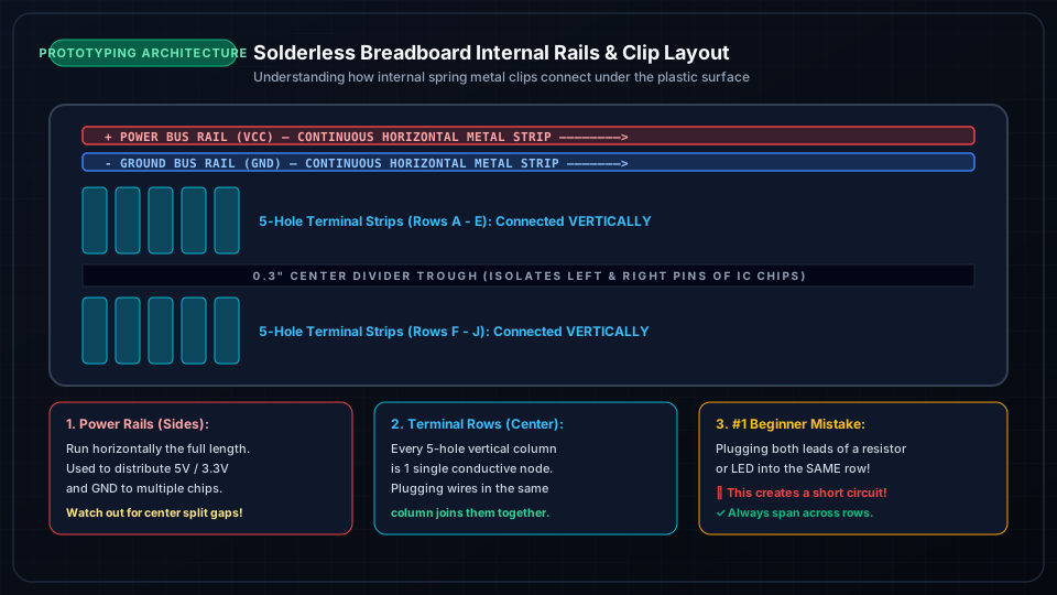
Solderless Breadboards: Internal Rail Connections
A Solderless Breadboard allows rapid electronic circuit prototyping without soldering:
- Power Rails (+ and -): Two long columns running vertically along both outer edges. All holes in a red (+) line are internally connected together; all holes in a blue (-) line are internally connected.
- Terminal Strips: The central grid rows (A-B-C-D-E and F-G-H-I-J). Each 5-hole horizontal row is internally bridged by spring-loaded metal clips.
- Center Divider Trough: Separates the two halves, perfectly sized to straddle 0.3" DIP IC chips so pins on opposite sides do not short together.
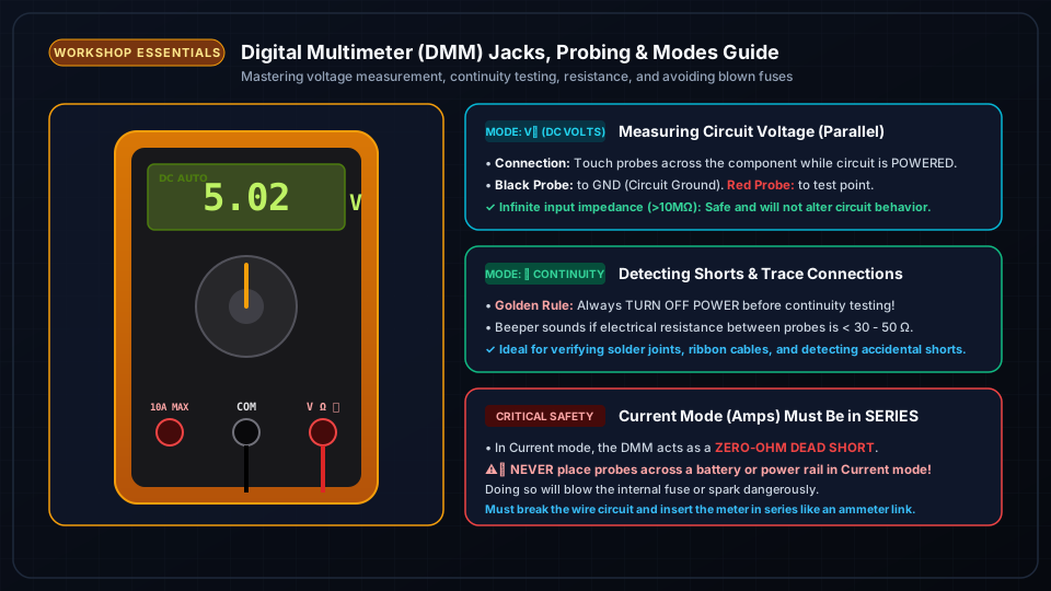
Digital Multimeter Guide: Voltage, Current, Resistance & Continuity
The Digital Multimeter (DMM) is the indispensable diagnostic tool of every electronics engineer:
- 1Measuring Voltage (DCV / ACV):
- Connect Black probe to COM and Red probe to V/Ω/mA.
- Place probes IN PARALLEL across the component while circuit is powered ON.
- 2Measuring Resistance (Ω):
- Turn circuit power OFF (disconnect battery).
- Place probes across the resistor.
- 3Continuity Beep Mode (🔊):
- Tests if two points are electrically connected with zero resistance. Beeper sounds on good wire connections, solder joints, or PCB traces.
- 4Measuring Current (Amperes / mA):
- WARNING: You must physically break the circuit loop and place the meter IN SERIES so current flows through the meter. Never measure voltage in current mode or you will blow the meter's internal fuse!
Frequently Asked Questions
What is the purpose of the center notch on a breadboard?
The center trough isolates the two sides of a standard 8-pin, 14-pin, or 16-pin DIP IC microchip, allowing you to access both rows of pins independently without shorting Pin 1 to Pin 8.
Why did my multimeter fuse blow when testing current?
In current mode, the multimeter has near-zero internal resistance. If you accidentally touch the probes across positive and negative power rails (parallel measurement instead of series), a dead short occurs and instantly blows the safety fuse.