Core Engineering Takeaways
- •Software can crash, freeze, or suffer memory corruption; safety-critical shutdowns must ALWAYS be backed by hardwired electromechanical interlocks.
- •Dual-channel E-Stops (Category 3/4) use two redundant normally-closed (NC) circuits monitored by microsecond pulse testing to instantly detect short circuits and welded contacts.
- •Safe Torque Off (STO) disables PWM gate drive pulses directly on MOSFET/IGBT gates, cutting motor torque in under 10 ms without killing logic power or losing encoder calibration.
- •Optocouplers and digital isolators prevent 48V motor surge spikes and ground loop noise from destroying sensitive 3.3V microcontrollers and microprocessors.
- •Hardware watchdog timers monitor software heartbeat signals; if firmware locks up in an infinite loop for 50 ms, the watchdog automatically forces a fail-safe reset.
- Basic DC electronics (relays, normally closed contacts, pull-up resistors)
- Microcontroller GPIO and interrupt basics
- Motor driver H-Bridge fundamentals
1. The Golden Rule: Why Software Alone Never Guarantees Safety
The most hazardous mistake in robotics engineering is trusting software to stop a moving machine.
Consider what happens if:
- Linux kernel encounters an Out-Of-Memory (OOM) lockup or freezes.
- A ROS 2 subscriber thread suffers priority inversion or deadlocks on a mutex.
- A solder whisker shorts the gate of a low-side MOSFET H-bridge to 12V.
If your "emergency stop" is a ROS topic command (/cmd_vel = 0), the robot continues driving at full speed into humans! Industrial robotics adheres to a strict Three-Tier Safety Hierarchy:
- 1Tier 1: Hardwired Hardware Interlocks (Pure Silicon & Copper): Dual safety relays, physical mushroom switches, electromechanical brakes. Functions even if all processors are completely destroyed.
- 2Tier 2: Real-Time Deterministic Firmware (Safety MCU): Bare-metal lockstep microcontrollers (e.g. TI Hercules, STM32F7 SIL-rated) running certified RTOS with watchdog timers.
- 3Tier 3: High-Level Software (ROS 2 / Linux): Software costmaps, obstacle zones, velocity clamping. Excellent for operational comfort, but never solely trusted for life-safety.
No safety function required to prevent catastrophic injury may depend solely on an operating system that is not certified for functional safety (such as standard Ubuntu Linux).
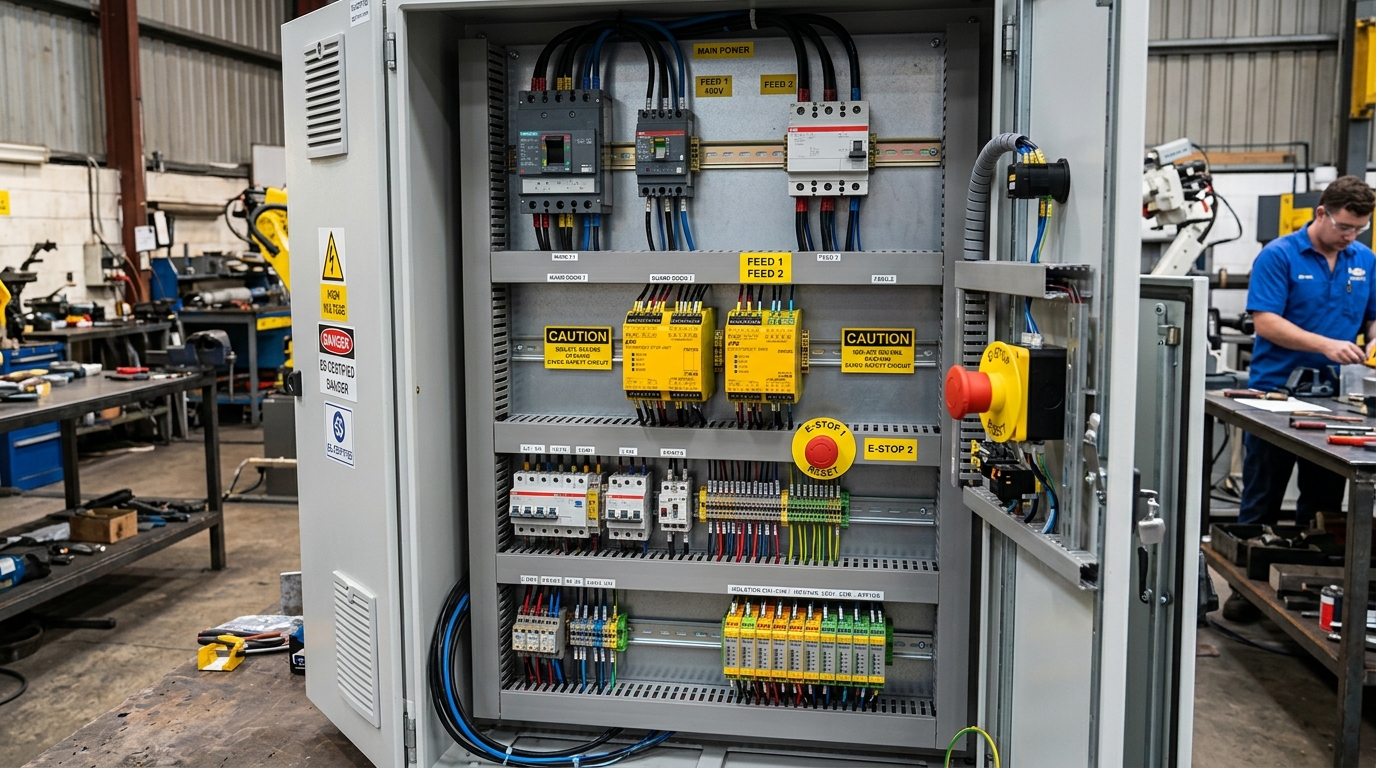
2. Dual-Channel E-Stop Circuits: Pulse Testing & Monitored Relays
A simple single-wire toggle switch is dangerous: if the wire gets pinched against the metal chassis and shorts to ground, pressing the switch does nothing!
Dual-Channel Monitored Wiring (ISO 13849 Category 4)
- Two Redundant Channels: The E-Stop button contains two separate mechanical contact blocks (NC1 and NC2) that open simultaneously when struck.
- Pulsed Test Outputs (Cross-Fault Detection): A dedicated safety relay outputs microsecond test pulses (e.g. Channel 1 = 100 Hz pulses, Channel 2 = 120 Hz pulses). If the two wires short together or short to ground, the safety relay detects the cross-talk within 2 milliseconds and trips the circuit.
- Manual Monitored Reset: Releasing the twist button must never automatically restart the robot! An operator must physically press a separate momentary illuminated Reset button to re-energize the safety contactor.
| Category (ISO 13849) | Channels | Fault Detection | Behavior on Single Fault | Industrial Acceptability |
|---|---|---|---|---|
| Category B | Single Channel | None | Loss of safety function | Unacceptable for automated mobile robots |
| Category 1 | Single Channel (Well-tried) | None | Loss of safety function possible | Low-risk bench testing only |
| Category 3 | Dual Channel | Detects single faults | Safety function maintained | Standard for warehouse AMRs and AGVs |
| Category 4 | Dual Channel + Test Pulses | Continuous cross-fault check | Safety function 100% guaranteed | Cobots, high-payload manipulators, heavy mobile equipment |
3. Safe Torque Off (STO) vs Main Power Cutoff vs Dynamic Braking
When an E-Stop trips, how do the motors actually stop?
1. Hard Power Contactor Cut (Brute Force)
A heavy electromechanical contactor cuts main DC battery voltage to the motor drivers.
- Problem: When a spinning motor is suddenly disconnected from the battery at high speed, high inductive voltage spikes () can arc across contactor contacts and destroy motor drivers. Microcontroller logic power is also lost.
2. Safe Torque Off (STO - Preferred Modern Architecture)
STO is a certified hardware feature built into modern motor drives (e.g. Elmo, Copley, ODrive Pro, Trinamic).
- Dual independent hardware pins cut off power to the gate driver optocouplers inside the inverter.
- The MOSFET gates drop to 0V within 5 milliseconds, meaning the motor physically cannot generate torque.
- Key Advantage: 48V bus power and 5V logic power remain active! Position encoders never lose their home calibration, and regenerative braking can still decelerate the robot cleanly before gates open.
3. Dynamic Braking & Spring-Applied Mechanical Brakes
- Dynamic Braking: Shorting all three motor phase wires together through low-resistance power resistors converts kinetic energy into heat via back-EMF, bringing the robot to an aggressive stop.
- Spring-Applied Brakes: In robotic arms and slope-rated AMRs, spring-applied friction brakes engage whenever power is lost, preventing the arm from crashing down due to gravity.
Maximum Inductive Flyback Voltage
4. Electrical Isolation: Optocouplers, Isolated DC-DC & Ground Loops
In mobile robots, electric motors draw 20 to 100+ Amps of current with high switching noise from PWM motor drivers.
If your motor driver ground and your Raspberry Pi / Jetson computer ground share a single continuous copper trace without isolation, motor return current flows through the delicate logic board traces. This creates ground bounce, corrupted I2C/SPI sensor packets, and randomly rebooting computers.
Solutions for Complete Galvanic Isolation:
- 1Optocouplers and Capacitive Digital Isolators (e.g. ISO7741): Separate logic signals (PWM, Direction, Step) into beams of light or RF electric fields across a 5,000V insulating barrier.
- 2Isolated DC-DC Converters: Separate the 24V/48V battery ground entirely from the 5V logic ground.
- 3Star Grounding: If grounds must tie together, connect them at exactly one single physical point directly at the battery negative terminal.
#include <stdint.h>
#include <stdbool.h>
#include "stm32f4xx_hal.h"

// Hardware Independent Watchdog (IWDG) Configuration
void Init_Hardware_Watchdog(void) {
    IWDG_HandleTypeDef hiwdg;
    hiwdg.Instance = IWDG;
    hiwdg.Init.Prescaler = IWDG_PRESCALER_64; // 32 kHz LSI clock / 64 = 500 Hz
    hiwdg.Init.Reload = 50;                   // 50 counts = 100 ms timeout window
    HAL_IWDG_Init(&hiwdg);
}

// Heartbeat refresh must be called from highest priority real-time loop
void Safety_Heartbeat_Loop(void) {
    if (Check_Sensors_Healthy() && Check_EStop_Closed()) {
        HAL_IWDG_Refresh(&hiwdg); // Reset watchdog countdown timer
    } else {
        // Deliberately starve watchdog: hardware resets system to fail-safe state in 100ms
    }
}
Note: Hardware Watchdog Timer implementation in embedded C. If software hangs or safety health checks fail, the watchdog timer starves and automatically forces hardware into a safe reboot.
5. Hardware Watchdogs & Safety Heartbeat Buses
A Watchdog Timer (WDT) is an independent hardware counter clocked by a separate internal RC oscillator. Once enabled, the counter counts down to zero.
If your main control software is functioning normally, it must periodically "kick" or "refresh" the watchdog before it reaches zero. If the software deadlocks, crashes, or gets trapped in an infinite loop, the counter expires and pulls the microcontroller reset pin low, triggering safe system reset.
CAN Bus Safety Heartbeat Protocol
For distributed robot architectures (Compute SBC Motor Controllers Power PDB):
- The central compute node broadcasts a heartbeat message on CAN ID
0x010every 20 milliseconds. - If motor controllers do not receive a valid heartbeat within 60 milliseconds (3 missed frames), they automatically drop into Safe Torque Off and clamp mechanical brakes.
Never refresh your watchdog from a low-priority background timer interrupt! Always refresh it from your actual main motor control loop. Otherwise, your main thread could freeze completely while the timer interrupt happily continues kicking the watchdog.
6. International Safety Standards: ISO 13849 Performance Levels (PL r) Explained
When commercial robots operate alongside human workers in factories, warehouses, or hospitals, adherence to international functional safety standards is mandatory by law:
- ISO 13849-1: Defines Performance Levels (PL a to PL e) based on:
- 1Category (B, 1, 2, 3, 4): Architectural structure and redundancy.
- 2MTTF_d (Mean Time to Dangerous Failure): Component reliability (Low, Medium, High).
- 3DC_avg (Diagnostic Coverage): Percentage of dangerous faults automatically detected by test pulses.
- ISO 10218-1 & ISO 10218-2: Safety requirements for industrial robots and robot integration.
- ISO 3691-4: The definitive European and international safety standard for Automated Guided Vehicles (AGVs) and Autonomous Mobile Robots (AMRs), requiring certified safety LiDARs with dynamic safety zones.
| Performance Level (PL) | Average Probability of Dangerous Failure / Hour (PFH_d) | Typical Severity of Risk | Target Robot Safety Application |
|---|---|---|---|
| PL a | 10^{-5} to 10^{-4} | Slight reversible injury | Auxiliary conveyor indicators |
| PL b | 3 × 10^{-6} to 10^{-5} | Minor reversible injury | Low-speed non-contact warning buzzers |
| PL c | 10^{-6} to 3 × 10^{-6} | Severe injury with low exposure | Small desktop educational robot arms |
| PL d | 10^{-7} to 10^{-6} | Severe permanent injury / fatality | Standard for warehouse AMRs (Safety LiDARs, STO) |
| PL e | 10^{-8} to 10^{-7} | Catastrophic mass casualty risk | Heavy industrial gantry arms, autonomous heavy earthmovers |
Common Questions & Troubleshooting
Q:Can I use an Arduino Uno or Raspberry Pi as my robot safety controller?
Never for human-safe industrial machines! Raspberry Pi runs a non-deterministic Linux OS that can freeze or suffer SD card corruption. Arduino Uno lacks dual-channel monitoring, lockstep cores, and memory protection units (MPU). For safety controllers, use certified safety relays (like Pilz, SICK, Phoenix Contact) or SIL-rated dual-core microcontrollers (like TI Hercules TMS570).
Q:What is the difference between a Normally Open (NO) and Normally Closed (NC) switch for safety?
Always use Normally Closed (NC) for safety! In an NC circuit, electrical current flows continuously when the machine is safe. If a wire breaks, becomes loose, or is severed by accident, current stops immediately—the exact same behavior as hitting the E-Stop. If you used a Normally Open (NO) switch and a wire broke, pressing the button would never make electrical contact, leaving the robot uncontrollable!
Q:What is the difference between Safe Torque Off (STO) and Safe Stop 1 (SS1)?
STO immediately cuts motor power, allowing the motor to coast to a stop under mechanical friction. Safe Stop 1 (SS1) first actively decelerates the motor to a complete standstill using controlled braking, and then automatically activates Safe Torque Off once zero speed is verified. SS1 is ideal for heavy mobile robots that take several meters to coast to a stop.