Core Engineering Takeaways
- •Microcontrollers provide hard real-time deterministic execution (sub-microsecond timing) that operating systems like Linux cannot guarantee.
- •GPIO pins have strict voltage and current thresholds (e.g., 20mA max on AVR, 12mA on ESP32); inductive loads must never be driven directly.
- •Hardware timers generate jitter-free PWM signals independently of the CPU core, freeing compute for sensor fusion and PID loops.
- •Interrupt Service Routines (ISRs) must execute in microseconds—never include delay(), serial printing, or heavy floating-point math inside an ISR.
- •Use ESP32 for wireless telemetry/web control, RP2040 for dual-core I/O via PIO state machines, STM32 for multi-axis industrial motion, and Arduino Uno for rapid electrical verification.
- Basic understanding of voltage, current, and Ohm's law
- Familiarity with basic C/C++ syntax (variables, functions, loops)
1. MCU vs SBC: Why Robots Need Deterministic Silicon
In modern robotics architectures, computing is split between two distinct tiers: Microcontrollers (MCUs) and Single Board Computers (SBCs) like the Raspberry Pi or NVIDIA Jetson.
The Problem of Determinism
A Single Board Computer runs a general-purpose operating system (Linux). Linux relies on a software scheduler that slices CPU time between hundreds of background processes, network daemons, and GUI rendering. When your robot is traveling at 2 meters per second and an obstacle sensor triggers, Linux might delay your motor-stop thread by 5 to 50 milliseconds while it handles an OS task. At high speeds, that 50ms delay equals 10 centimeters of unchecked travel—resulting in a physical collision.
A Microcontroller, in contrast, runs bare-metal firmware or a lightweight Real-Time Operating System (FreeRTOS). It executes instructions on a clock-cycle level with sub-microsecond determinism. When an interrupt fires on an MCU pin, hardware registers switch instantly and the safety stop executes within nanoseconds.
Never drive motors or read safety limit switches directly from an SBC operating system. Let the MCU handle the physical motor loops and sensor inputs, and let the SBC send high-level velocity commands (cmd_vel) over USB-serial, CAN, or Ethernet.
| Specification | Microcontroller (MCU) | Single Board Computer (SBC) |
|---|---|---|
| Primary Role | Real-time motor control, sensor polling, safety stops | Computer vision, SLAM, motion planning, ROS 2 |
| Operating System | Bare-metal C/C++ or FreeRTOS | Full Linux OS (Ubuntu, Debian, Yocto) |
| Timing Determinism | Hard real-time (sub-microsecond jitter) | Soft real-time (milliseconds of scheduling jitter) |
| Clock Frequencies | 16 MHz to 480 MHz | 1.2 GHz to 2.6 GHz (Multi-core 64-bit) |
| RAM Memory | 2 KB to 1 MB (On-chip SRAM) | 1 GB to 16 GB (LPDDR4/DDR5) |
| Boot Time | < 50 milliseconds (Instant-on) | 15 to 45 seconds cold boot |
| Power Draw | 0.05W to 0.5W | 5W to 25W+ (Requires heatsinks/fans) |
| Direct I/O Access | Hardware registers, direct timer & pin control | Kernel device drivers, memory mapping, /dev interfaces |
2. MCU Core Anatomy: CPU, Flash, SRAM & Registers
Understanding how an MCU handles code execution helps roboticists write faster, jitter-free control loops.
The Memory Hierarchy
- 1Flash ROM (Non-Volatile Storage): Holds your compiled program binary and bootloader. It retains its contents when power is disconnected, but writing to Flash during runtime is slow.
- 2SRAM (Static RAM - Volatile): The ultra-fast workspace where the CPU stores dynamic variables, the call stack, sensor buffers, and PID state variables. If power is removed, SRAM is wiped clean.
- 3Special Function Registers (SFRs): Memory-mapped hardware control words. Writing a single bit to an SFR changes physical silicon behavior—such as toggling an output pin high, resetting a hardware timer, or clearing an interrupt flag.
Harvard vs. Von Neumann Architecture
Most modern robotics microcontrollers (AVR, ARM Cortex-M, Xtensa) utilize a modified Harvard Architecture, separating the instruction bus from the data bus. This enables the CPU core to fetch the next instruction opcode at the exact same instant it reads sensor data from SRAM, achieving 1 clock cycle per instruction efficiency.
3. Essential Peripherals: GPIO, ADC & Hardware PWM
Robots interact with the physical universe through dedicated silicon peripherals built onto the MCU die:
1. General Purpose Input/Output (GPIO)
GPIO pins can be configured in software as:
- Digital Output (Push-Pull): Actively drives the pin to VCC (Logic High) or GND (Logic Low).
- Digital Output (Open-Drain): Only pulls to GND; requires an external pull-up resistor to reach High. Essential for shared buses like I2C.
- Digital Input (High-Impedance / Floating): Consumes virtually zero current (< 1µA) while reading the logic state.
- Input with Internal Pull-Up/Pull-Down: Connects a high-value resistor (~20kΩ to 50kΩ) internally to prevent floating inputs when buttons or microswitches are unpressed.
2. Analog-to-Digital Converter (ADC)
Microcontrollers are digital computers, but physical sensors (IR proximity detectors, potentiometers, thermistors) produce continuously variable analog voltages. The ADC quantizes this voltage into discrete integers.
- Resolution (Bits): Determines the smallest detectable voltage step (). An 8-bit ADC has 256 steps; a 10-bit ADC has 1024 steps; a 12-bit ADC has 4096 steps.
- Sampling Rate: The frequency at which analog signals can be measured (typically 100 kSPS to 1 MSPS on modern ARM chips).
3. Hardware Pulse-Width Modulation (PWM) Timers
DC motor speed and hobby servo positions are governed by high-frequency PWM. Rather than having CPU software manually toggle a pin on and off, dedicated hardware timers increment a counter register at high frequencies (e.g. 20 kHz) and toggle the pin automatically when the counter matches a compare value. The CPU is completely free to run control code while the hardware timer produces continuous, jitter-free motor driving pulses.
ADC Voltage Quantization Equation
On a 12-bit ADC (N=12, 4095 steps) with 3.3V reference, an analog distance sensor reading of 2048 corresponds to: (2048 / 4095) * 3.3V = 1.65 Volts.
Hardware PWM Duty Cycle & Average Voltage
A 12V motor powered with a 75% duty cycle PWM receives an effective average voltage of: 12V * 0.75 = 9.0 Volts.
4. Hardware Interrupts (ISRs) & Real-Time Motor Control
When a mobile robot travels across a floor, optical wheel encoders generate thousands of digital pulses per second. If you poll these pins using an if (digitalRead(pin)) inside a software loop, your program will miss counts whenever it is busy computing math or updating an OLED screen.
How Interrupts Work
A Hardware Interrupt monitors a physical pin at the silicon transistor level. When a rising or falling edge occurs:
- 1The hardware CPU suspends current instruction execution immediately.
- 2The current register state is pushed onto the stack.
- 3The program counter jumps to the Interrupt Service Routine (ISR) function.
- 4The ISR increments the encoder counter in 10 to 50 clock cycles.
- 5The CPU restores its previous registers and resumes the main code without missing a single tick.
The 4 Cardinal Rules of Writing ISRs:
- 1Keep it Ultra-Short: Only read hardware pins, increment counters, or set volatile flags.
- 2Never Call Delay Functions: Functions like
delay()ordelayMicroseconds()freeze system timers inside an ISR. - 3Declare Shared Variables as
volatile: Thevolatilekeyword tells the C++ compiler that this memory address can change asynchronously outside the main thread, preventing improper compiler register caching. - 4Guard Multi-Byte Variable Reads: In your main loop, reading a 32-bit integer (
int32_t) takes multiple clock cycles on an 8-bit MCU. Disable interrupts briefly (noInterrupts()) while copying the value to prevent the ISR from modifying the number mid-read.
// Deterministic Optical Quadrature Encoder Counter via Hardware Interrupts
const uint8_t ENCODER_PIN_A = 2; // Must be an external interrupt pin
const uint8_t ENCODER_PIN_B = 3;

// volatile keyword guarantees compiler never caches count in a CPU register
volatile int32_t encoderTicks = 0;

void IRAM_ATTR handleEncoderInterrupt() {
  // Rapid state evaluation of channel B determines rotation direction
  if (digitalRead(ENCODER_PIN_B) == HIGH) {
    encoderTicks++;
  } else {
    encoderTicks--;
  }
}

void setup() {
  Serial.begin(115200);
  pinMode(ENCODER_PIN_A, INPUT_PULLUP);
  pinMode(ENCODER_PIN_B, INPUT_PULLUP);

  // Attach ISR on rising edge of Channel A
  attachInterrupt(digitalPinToInterrupt(ENCODER_PIN_A), handleEncoderInterrupt, RISING);
}

void loop() {
  // Atomic read of multi-byte volatile variable
  noInterrupts();
  int32_t currentTicks = encoderTicks;
  interrupts();

  Serial.print("Current Wheel Position: ");
  Serial.println(currentTicks);
  delay(50); // Safe to delay in main loop; interrupt continues counting in hardware!
}
Note: This code illustrates how wheel encoder ticks are captured flawlessly in the background using hardware interrupts while the main loop runs at its own relaxed schedule.
5. The Big Four: Arduino, ESP32, Pico & STM32
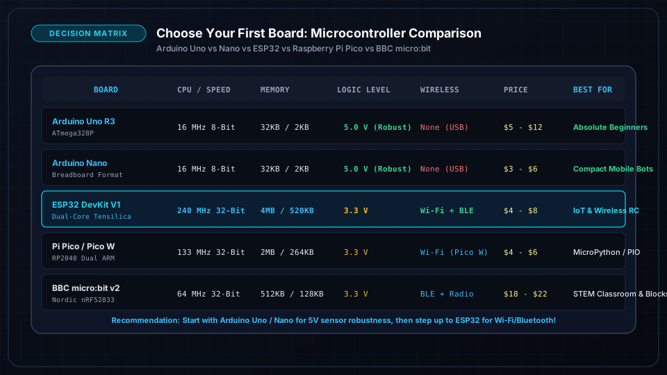
Modern robotics engineering relies predominantly on four microcontroller families, each excelling in a specific robotics niche:
1. Arduino (AVR ATmega328P / Mega 2560)
- Strengths: Bulletproof 5V logic tolerance. If you accidentally short 5V to a digital pin, the ATmega usually survives. Massive community library ecosystem.
- Weaknesses: 8-bit 16MHz processor, tiny 2KB SRAM, no native floating-point hardware. Struggles with complex kinematic inverse trigonometry or multi-sensor filtering.
- Best Use: Basic 2-wheel rovers, introductory high school robotics, relay switching boards.
2. Espressif ESP32 (Xtensa Dual-Core & RISC-V)
- Strengths: 240 MHz dual-core horsepower, integrated 2.4GHz Wi-Fi and Bluetooth LE, 520 KB SRAM, FreeRTOS dual-core task pinning. One core handles motor PID while the other serves real-time WebSocket telemetry!
- Weaknesses: 3.3V logic (NOT 5V tolerant), noisy analog ADC requires calibration curves.
- Best Use: Wi-Fi teleoperated rovers, IoT robotic arms, ESP-NOW distributed robot swarms.
3. Raspberry Pi Pico (RP2040 / RP2350)
- Strengths: Dual ARM Cortex-M0+ / M33 cores at 133MHz+, 264KB SRAM, and the revolutionary Programmable I/O (PIO) state machines. PIO allows you to create custom hardware protocols (DMX, custom stepper step-direction generators, WS2812 drivers) that run 100% autonomously without touching CPU cycles.
- Weaknesses: No built-in Wi-Fi on base model (Pico W adds 2.4GHz), 3.3V logic.
- Best Use: Multi-motor stepper controllers, complex sensor hubs, education, and MicroPython prototyping.
4. STMicroelectronics STM32 (ARM Cortex-M0/M4/M7)
- Strengths: Industrial gold standard. Advanced timer arrays with hardware quadrature encoder decoding modes, integrated CAN bus controllers, FPU (Floating Point Unit) for instantaneous inverse kinematics math, hardware DMA (Direct Memory Access).
- Weaknesses: Steeper learning curve; configuring clock trees and HAL drivers requires STM32CubeIDE.
- Best Use: Drone flight controllers (Betaflight), industrial robotic arm joints, high-speed quadruped leg actuators, CAN-networked mobile bases.
| Specification | Arduino Uno R3 | ESP32 DevKit V1 | Raspberry Pi Pico | STM32F401 BlackPill |
|---|---|---|---|---|
| Processor Core | 8-bit AVR RISC | 32-bit Dual Xtensa LX6 | 32-bit Dual Cortex-M0+ | 32-bit ARM Cortex-M4 + FPU |
| Clock Speed | 16 MHz | 240 MHz | 133 MHz (Overclockable) | 84 MHz |
| Flash Memory | 32 KB | 4 MB (SPI Flash) | 2 MB (QSPI Flash) | 512 KB |
| SRAM (RAM) | 2 KB | 520 KB | 264 KB | 96 KB |
| Operating Voltage | 5.0V (5V Tolerant) | 3.3V (3.3V Max) | 3.3V (3.3V Max) | 3.3V (5V Tolerant on most pins) |
| ADC Resolution | 10-bit (1024 steps) | 12-bit (Non-linear) | 12-bit (Effective ~10b) | 12-bit (Fast & Linear) |
| Hardware Timers | 3 Timers (6 PWM) | 4 Timers (16 LEDC PWM) | 8 Timers (16 PWM) | 6 Advanced Timers (Encoder mode) |
| Wireless Connectivity | None | Wi-Fi 4 + BLE 4.2 | None (Pico W has Wi-Fi) | None (External transceiver) |
| Typical Price | 22 | 7 | 6 | 6 |
| Primary Specialty | Education & 5V circuits | Wireless rovers & telemetry | PIO custom timing & state machines | High-performance motion & drones |
6. Engineering Selection Matrix: Matching MCU to Robot Type
Choosing the wrong microcontroller leads to jittery servos, dropped sensor packets, and sluggish control. Follow this architectural decision tree:
1. Two-Wheeled Obstacle Avoider or Line Follower
- Recommended: Arduino Uno / Nano or RP2040 Pico
- Why: Simple 2-motor differential drive with basic IR sensors and ultrasound requires low compute. 5V logic compatibility simplifies sensor wiring.
2. Wireless Teleoperated Mobile Rover / Inspection Bot
- Recommended: ESP32
- Why: Built-in Wi-Fi allows direct WebSocket or HTTP streaming of sensor data and joystick control from any web browser without needing expensive external radio shields.
3. Multi-Axis 6-DOF Robotic Arm
- Recommended: STM32F4 / F7 or Teensy 4.1
- Why: Computing real-time 6x6 Jacobian matrices, trigonometric inverse kinematics, and simultaneous multi-stepper acceleration profiles requires a hardware Floating Point Unit (FPU) and multi-channel hardware timers.
4. Drone / Quadcopter Flight Controller
- Recommended: STM32F405 / STM32F722
- Why: 8 kHz gyro sensor polling over high-speed SPI, combined with quaternion orientation estimation and 400 Hz motor DShot protocol generation, requires dedicated ARM Cortex-M hardware timers and DMA.
On advanced robots, never hesitate to use two controllers: An STM32 or RP2040 dedicated exclusively to low-level motor PID loops, communicating via UART or CAN bus with an ESP32 or Raspberry Pi handling wireless networking and high-level autonomous logic.
Common Questions & Troubleshooting
Q:Can I power a 5V servo motor directly from an Arduino or ESP32 5V pin?
Only for a single micro servo (like an SG90) with no mechanical load during quick testing. A standard hobby servo pulls 500mA to 1.5A when stalling or accelerating. The on-board voltage regulator on your MCU development board can only provide 200mA to 800mA total before overheating, causing voltage brownouts that reset your microcontroller. Always power servos from an external 5V-6V battery or buck converter with a shared common ground.
Q:Why are ESP32 pins labeled 3.3V, and will 5V sensors destroy it?
Yes, feeding 5V into an ESP32 or RP2040 GPIO pin can permanently burn out the internal silicon protection diodes. When connecting 5V sensors (like the HC-SR04 ultrasonic echo pin), use a simple 2-resistor voltage divider (1kΩ and 2kΩ) or a bidirectional logic level shifter module to step down the signal to 3.3V safely.
Q:What is the advantage of Raspberry Pi Pico PIO (Programmable I/O) in robotics?
PIO gives you 8 miniature state machines that execute simple assembly instructions independently of the main CPU cores. You can use PIO to read 4 quadrature optical encoders at megahertz frequencies or generate precise pulse trains for 16 stepper motors simultaneously without utilizing any CPU cycles.