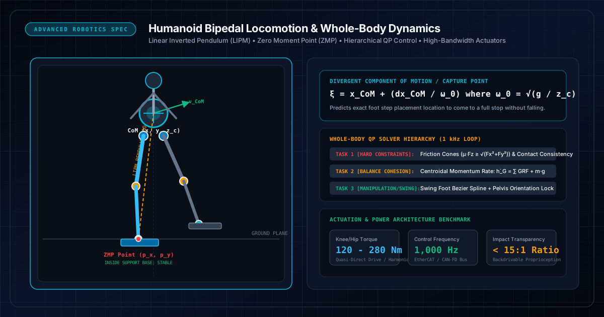
Core Engineering Takeaways
- •Static stability (keeping the Center of Mass over the footprint) fails for dynamic walking; bipedal robots rely on dynamic stability where the Zero Moment Point (ZMP) remains strictly within the active support polygon.
- •The Linear Inverted Pendulum Model (LIPM) constrains Center of Mass height to a constant horizontal plane ($z_c = \text{const}$), linearizing non-linear multi-body equations into decoupled second-order differential equations.
- •The Capture Point (or Divergent Component of Motion) identifies the exact spatial coordinates where the robot must plant its swing foot to arrest forward momentum and come to a complete standstill.
- •Whole-Body Control (WBC) formulates robot balance as a multi-objective Quadratic Program (QP) solved at 1 kHz, prioritizing contact friction cones and balance ahead of upper-body arm manipulation.
- •Actuator transparency (low gear reduction $< 15:1$ and low rotor inertia) is critical for legged robots to absorb foot ground impacts without breaking gears while sensing contact forces proprioceptively via motor current.
- Rigid body dynamics (Newton-Euler equations, inertia tensors, Coriolis matrices)
- State-space control theory (LQR, linear state observers, eigenvalues)
- Numerical optimization (Quadratic Programming, Karush-Kuhn-Tucker conditions)
1. Physics of Bipedal Locomotion: The Linear Inverted Pendulum Model (LIPM)
Humanoid robots walk by continuously executing controlled falling.
A 30+ degree-of-freedom humanoid robot involves complex non-linear dynamics governed by the standard multi-body equation:
Directly solving this full equation for dynamic step trajectories in real-time is computationally intractable.
The Linear Inverted Pendulum Simplification (LIPM)
Pioneered by Kajita et al., the LIPM assumes the robot's entire mass is concentrated at a single Center of Mass (CoM) point supported by a massless, variable-length leg.
By enforcing a constant CoM height (), the vertical acceleration , completely decoupling the horizontal dynamics:
Where:
- is the natural frequency of the inverted pendulum.
- is the ground position of the support foot (the Center of Pressure / ZMP).
- This simple linear ordinary differential equation can be solved analytically in real-time!
LIPM Natural Frequency & Analytical CoM State Trajectory
For a humanoid robot with CoM height z_c = 0.85 m: ω_0 = √(9.81 / 0.85) = 3.397 rad/s. A step cycle of 0.4 seconds causes hyperbolic divergence of ~2.1x initial velocity displacement.
2. Dynamic Stability Criteria: Zero Moment Point (ZMP) & Capture Point
How does a robot know whether it is about to tip over?
1. The Zero Moment Point (ZMP)
The Zero Moment Point is defined as the point on the ground where the horizontal components of the tipping moment generated by gravity and inertial forces equal zero:
- Stability Condition: As long as the calculated ZMP point lies strictly inside the geometric interior of the support polygon (the convex hull of the foot sole or feet in double support), the robot sole will not pivot or roll over its edges.
- If external disturbances push the desired ZMP outside the support polygon, the foot begins tipping over its toe or heel.
2. The Capture Point (Divergent Component of Motion - DCM)
While ZMP measures instantaneous equilibrium, the Capture Point () measures dynamic momentum. It represents the point on the ground where the robot must step to come to a complete rest:
If a strong push propels the robot forward, the capture point instantly projects forward outside the current foot base. The footstep planner immediately commands the swing foot to land directly on the capture point, restoring dynamic stability.
Small balance perturbations (< 10 N) are resisted purely by ankle joint torques shifting the ZMP within the sole. Moderate perturbations trigger hip angular accelerations (generating restoring angular momentum). Severe pushes move the Capture Point outside the sole, requiring an immediate recovery step.
3. Whole-Body Control (WBC): Hierarchical Quadratic Programming (HQP)
A humanoid walking on dynamic terrain cannot treat joints independently; moving an arm or shifting torso angle exerts reactive reaction forces on the stance leg.
Whole-Body Control (WBC) coordinates all degrees of freedom simultaneously using a Hierarchical Quadratic Program (HQP) solved at 1 kHz:
Subject to strict physical inequality and equality constraints:
- 1Equations of Motion: .
- 2Contact Consistency: (stance feet must not penetrate or slide on the floor).
- 3Coulomb Friction Cone: and (ground cannot pull on feet).
- 4Hardware Torque Limits: and joint angle limits.
By organizing objectives into a strict hierarchy (Null-Space Projection), safety constraints and balance cohesion take absolute priority over auxiliary gestures or camera tracking.
Industrial WBC implementations rely on lightweight C++ Quadratic Program solvers like qpOASES, ProxQP, or OSQP. The QP optimization must converge in less than 300–500 microseconds to leave sufficient overhead for EtherCAT bus transmission.
4. Actuator Architectures: Quasi-Direct Drive (QDD) vs Harmonic Reduction
Traditional industrial robot arms use high gear ratio () strain wave (Harmonic Drive) gearboxes. However, applying these to humanoid legs results in catastrophic gear tooth breakage during running or jumping due to high reflected rotor inertia:
Where is the gear reduction ratio! At , the motor rotor appears 10,000 times heavier to external foot impacts!
Modern Actuator Paradigms for Legged Robotics:
- 1Quasi-Direct Drive (QDD):
- High-diameter, high-pole-count brushless outrunner motor paired with a single-stage planetary gear ( to ).
- Extremely low reflected inertia and highly backdrivable.
- Enables proprioceptive force sensing: contact forces on the foot sole reflect directly back to the motor coils, allowing accurate force measurement from motor current alone without fragile 6-axis foot sensors.
- Used in MIT Cheetah, Unitree H1/G1, and agile research bipeds.
- 2High-Torque Planetary & Harmonic Actuators:
- Utilized where extreme peak torque density is mandatory (e.g. humanoid hips and knees delivering ).
- Must be paired with high-bandwidth strain-gauge torque sensors or series elastic compliance (SEA) to protect gear teeth from dynamic shock loads.
| Actuator Type | Gear Ratio (N) | Impact Transparency | Torque Density | Force Sensing Method |
|---|---|---|---|---|
| Quasi-Direct Drive (QDD) | 6:1 to 10:1 | Exceptional (> 90% backdrivable) | Moderate (30 - 60 Nm/kg) | Proprioceptive motor phase current |
| Planetary (2-Stage) | 15:1 to 30:1 | Good (Partially backdrivable) | High (60 - 90 Nm/kg) | Current + joint encoder deflection |
| Harmonic Drive (Strain Wave) | 80:1 to 160:1 | Zero (Rigid / Non-backdrivable) | Very High (100+ Nm/kg) | Requires dedicated joint torque sensor |
| Linear Electro-Hydrostatic (EHA) | Variable fluid ratio | Moderate | Extreme (> 150 Nm/kg) | Hydraulic chamber pressure transducers |
5. Model Predictive Control (MPC) & Real-Time Gait Generation
While Whole-Body Control computes instantaneous millisecond joint torques, a high-level Model Predictive Controller (MPC) looks into the future across a time horizon of 1.0 to 1.5 seconds (2–3 walking steps).
Convex MPC Formulation
At every control cycle (typically 50–100 Hz), the MPC solves:
- 1Predicting future Center of Mass trajectory over horizon intervals.
- 2Optimizing discrete foot contact locations and contact timing.
- 3Calculating required continuous Ground Reaction Forces (GRFs) to smoothly track user joystick velocity commands.
When the robot detects an unexpected obstacle or slip, the MPC instantly adapts future step placement in the next 10 ms optimization cycle, steering the swing foot to safe footholds.
Convex MPC Cost Function for Centroidal Locomotion
Optimizes a 20-step horizon at dt = 25 ms, recalculating the entire footstep and force trajectory at 40 Hz.
6. Hardware Stacks & Sim-to-Real: 1 kHz EtherCAT, MuJoCo & Isaac Gym
Deploying bipedal locomotion algorithms to physical titanium and carbon fiber hardware requires an ultra-reliable, deterministic real-time communication stack.
1. Real-Time Hardware Communication: EtherCAT & CAN-FD
Standard Ethernet (TCP/UDP) introduces jitter of 1–10 ms, which will cause a humanoid robot to stumble and crash.
- Production humanoids use EtherCAT (Ethernet for Control Automation Technology) or multi-channel CAN-FD at 1,000 Hz.
- A PREEMPT_RT patched Linux kernel guarantees deterministic interrupt execution with jitter.
2. Sim-to-Real Training via Reinforcement Learning (RL)
Modern humanoid research increasingly trains end-to-end locomotion policies in massively parallel physics simulators:
- NVIDIA Isaac Gym / Isaac Lab: Simulates 4,096 robot instances in parallel on a single GPU.
- Domain Randomization: Perturbs mass distributions, friction coefficients, actuator latency, and motor damping during training.
- Policies trained in simulation transfer directly (Zero-Shot Sim-to-Real) to physical hardware, robustly walking across gravel, grass, and staircases.
#include <chrono>
#include <thread>
#include <sched.h>
#include <sys/mman.h>
#include <rclcpp/rclcpp.hpp>
void configure_realtime_thread() {
// Lock memory to prevent page faults during execution
mlockall(MCL_CURRENT | MCL_FUTURE);
// Set FIFO real-time priority
sched_param param;
param.sched_priority = 95; // Real-time priority (1-99)
pthread_setschedparam(pthread_self(), SCHED_FIFO, ¶m);
}
void run_1khz_whole_body_control() {
configure_realtime_thread();
using namespace std::chrono;
auto next_wakeup = high_resolution_clock::now();
const nanoseconds cycle_period(1000000); // 1 ms = 1,000 Hz
while (true) {
next_wakeup += cycle_period;
// 1. Read EtherCAT Joint Sensors (Encoders, Currents, IMU)
// read_ethercat_bus_pdo();
// 2. Solve 1 kHz Whole-Body QP Controller
// Eigen::VectorXd commanded_torques = solve_hierarchical_qp();
// 3. Write Motor Torques to Inverter Drives
// write_ethercat_bus_pdo(commanded_torques);
// Sleep precisely until next 1 ms boundary
std::this_thread::sleep_until(next_wakeup);
}
}Note: Real-time 1 kHz PREEMPT_RT control loop executing QP Whole-Body Control on EtherCAT joint drives.
Common Questions & Troubleshooting
Q:Why do humanoid robots require a 1 kHz control loop while mobile wheeled robots operate at 50 Hz?
Wheeled robots have large, statically stable contact footprints that do not spontaneously tip over if a control cycle is delayed by 20 ms. Humanoid robots are inherently unstable inverted pendulums supported by narrow foot edges; ground contact impacts, ankle compliance, and friction cone stabilization require sub-millisecond reaction times to avoid catastrophic falls.
Q:What is the physical meaning of the Capture Point in simple terms?
The Capture Point is the exact spot on the floor you would naturally step onto if someone shoved you forward while standing. If you plant your foot directly onto that point, your forward kinetic energy is completely absorbed by gravitational potential energy, and you come to an immediate halt without taking another step.
Q:Why are Harmonic Drive gearboxes risky for humanoid walking legs?
Harmonic drives use a thin, flexible elliptical steel cup (flexspline). Because they have very high gear reductions (> 80:1), external shock impacts on the foot (such as heel strikes on concrete) cannot backdrive the motor rotor quickly enough, dumping immense instantaneous shock torques directly onto the flexspline teeth, resulting in rapid mechanical shear.
Q:How do Reinforcement Learning policies compare with classical QP Whole-Body Controllers?
Classical model-based WBC provides strict mathematical safety guarantees, exact contact force limits, and predictable behavior. Reinforcement Learning policies excel at traversing rough, unstructured terrain, recovering from violent pushes, and adapting to dynamic terrain compliance that is difficult to model explicitly. State-of-the-art robots increasingly combine both: an RL policy generates reference trajectories, which a low-level QP WBC executes with strict safety constraints.