Core Engineering Takeaways
- •Testing navigation and manipulator motion planning in simulation prevents physical motor burnouts and hardware collisions during early software testing.
- •Gazebo Harmonic (formerly Ignition) is the open-source industry standard for ROS 2, while NVIDIA Isaac Sim utilizes RTX ray tracing and GPU physics for million-step reinforcement learning.
- •URDF describes kinematic trees using Links and Joints; Xacro macros prevent copy-paste bugs by parameterizing wheel dimensions and joint limits.
- •Incorrect inertial tensors $(I_{xx}, I_{yy}, I_{zz})$ in your URDF cause simulation physics solvers to explode or vibrate uncontrollably.
- •The "Sim-to-Real Gap" is bridged using Domain Randomization (varying mass, friction, sensor noise) and System Identification (measuring real motor step response).
- Rigid body mechanics (mass centers, moments of inertia)
- XML syntax and ROS 2 launch file patterns
- Basic 3D mesh formats (STL, DAE, OBJ)
1. Why Simulation First? The True Cost of Hardware Crashes
In robotics, writing code directly on real physical hardware is reckless:
- A software sign error in your motor PID loop can send a 30 kg robot charging into a glass wall at 3 m/s.
- Tuning a quadruped robot's walking policy in the physical world burns servo motor gears in 15 minutes.
- Re-flashing and testing algorithms on real robots takes minutes per test; headless simulation runs 1,000 tests concurrently in a cloud CI/CD container within seconds.
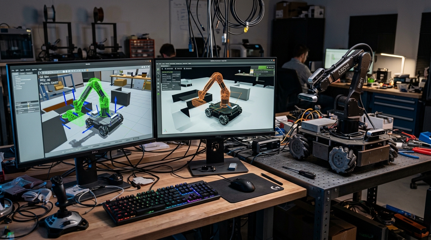
A Digital Twin is an accurate virtual model of your robot operating in a simulated environment with identical mass properties, kinematics, sensor interfaces, and communications. Code written for the simulated robot in ROS 2 should run on the real robot without changing a single line of software!
Never run autonomous navigation or arm trajectory software on real physical hardware until it has successfully completed at least 50 continuous collision-free runs in simulation.
2. The Modern Simulator Landscape: Gazebo, Isaac Sim, MuJoCo & Webots
The robotics ecosystem has evolved beyond legacy Gazebo Classic (Gazebo 11, which reached End-of-Life in 2025):
- 1Gazebo Harmonic (Open Source / Open Robotics):
- Modern modular rewrite of Gazebo with clean C++ plugin architecture (Gz Transport, Gz Sim).
- Fully integrated into ROS 2 Jazzy and Humble via
ros_gz_bridge. - Supports multiple physics engines (DART, Bullet, ODE).
- 2NVIDIA Isaac Sim (GPU-Accelerated / Omniverse):
- Built on Pixar Universal Scene Description (OpenUSD) and NVIDIA PhysX 5.
- Runs photorealistic RTX real-time ray-tracing (sub-surface scattering, lighting, lens distortions).
- Capable of simulating 10,000 robots simultaneously on GPU for reinforcement learning.
- 3MuJoCo (Multi-Joint dynamics with Contact):
- Created for fast, convex contact dynamics and biomechanics; now open-source under Google DeepMind.
- Ideal for humanoids, bipedal balance, and robotic dexterous manipulation.
| Simulator | Primary Physics Engine | Rendering Quality | ROS 2 Native Bridge | Best Used For |
|---|---|---|---|---|
| Gazebo Harmonic | DART / Bullet | Good (Ogre 2 Engine) | Yes (ros_gz_bridge) | Mobile robots, ROS 2 Nav2, standard academic labs |
| NVIDIA Isaac Sim | PhysX 5 (GPU Solver) | Photorealistic (RTX) | Yes (Isaac ROS & USD) | Perception training, synthetic data, multi-robot fleets |
| MuJoCo | MuJoCo Convex Contact | Minimal (OpenGL) | Third-Party wrappers | Reinforcement learning, legged locomotion, grasping |
| Webots | ODE (Modified) | Moderate | Yes (Built-in ROS 2) | Quick educational prototypes and multi-agent swarms |
3. Modeling Robot Geometry: URDF, Xacro Macros & OpenUSD
Robots are mathematically described as kinematic trees of Links (rigid bodies) connected by Joints (revolute, continuous, prismatic, fixed).
Visual vs Collision Geometry
Never use high-poly visual meshes (100,000 triangles CAD export) for collision physics!
- Visual Mesh: Detailed STL or DAE mesh with textures, logos, and bevels for realistic screen rendering.
- Collision Mesh: Primitive cylinders, boxes, or low-poly convex hulls (<500 triangles). Physics engines calculate collisions every 1 millisecond; complex meshes cause simulation frame rates to collapse.
Xacro (XML Macros)
Writing raw URDF files leads to thousands of repetitive lines. Xacro adds variables, math expressions, and reusable macros:
<?xml version="1.0"?>
<robot xmlns:xacro="http://www.ros.org/wiki/xacro" name="diff_rover">
  <xacro:property name="wheel_radius" value="0.08"/>
  <xacro:property name="wheel_width" value="0.04"/>
  <xacro:property name="wheel_mass" value="0.6"/>

  <!-- Reusable Wheel Macro -->
  <xacro:macro name="wheel_link" params="prefix reflect">
    <link name="${prefix}_wheel">
      <visual>
        <geometry><cylinder radius="${wheel_radius}" length="${wheel_width}"/></geometry>
        <material name="black"/>
      </visual>
      <collision>
        <geometry><cylinder radius="${wheel_radius}" length="${wheel_width}"/></geometry>
      </collision>
      <inertial>
        <mass value="${wheel_mass}"/>
        <inertia ixx="${(1/12)*wheel_mass*(3*wheel_radius*wheel_radius + wheel_width*wheel_width)}"
                 iyy="${(1/12)*wheel_mass*(3*wheel_radius*wheel_radius + wheel_width*wheel_width)}"
                 izz="${(1/2)*wheel_mass*wheel_radius*wheel_radius}"
                 ixy="0" ixz="0" iyz="0"/>
      </inertial>
    </link>

    <joint name="${prefix}_wheel_joint" type="continuous">
      <parent link="base_link"/>
      <child link="${prefix}_wheel"/>
      <origin xyz="0 ${reflect * 0.18} 0" rpy="-${pi/2} 0 0"/>
      <axis xyz="0 0 1"/>
    </joint>
  </xacro:macro>

  <xacro:wheel_link prefix="left" reflect="1"/>
  <xacro:wheel_link prefix="right" reflect="-1"/>
</robot>
Note: Parametric Xacro file demonstrating wheel macro instantiation with analytical cylinder moment of inertia formulas and continuous revolute joints.
4. Physics Engine Realism: Inertial Tensors, Solvers & Contact Dynamics
The single most common bug in beginner robot simulations is phantom vibrating or robots flying into space. This almost always results from zero or unphysical moments of inertia!
Every dynamic link must have an accurate symmetric moment of inertia matrix:
Modern CAD tools (Fusion 360, SolidWorks, Onshape) calculate the exact center of mass and moment of inertia matrix around the link origin with a single click.
Solid Box Moment of Inertia Tensor
5. Realistic Sensor Simulation: Ray-Traced LiDAR, Cameras & IMU Noise
Perfect simulated sensors teach bad programming habits! In a simulator, an simulated LiDAR never gets blinded by the sun, and an simulated IMU has zero drift. If you tune an algorithm on perfect sensors, it fails immediately on real hardware.
To create high-fidelity sensor models in Gazebo or Isaac Sim:
- LiDAR Noise: Add Gaussian noise to range readings and set a realistic minimum range (0.15 m).
- IMU Bias Drift: Configure gyroscope random walk and accelerometer white noise parameters.
- Camera Drops: Simulate real USB / MIPI frame rate jitter and exposure motion blur.
| Sensor Type | Plugin Name | Noise Type | Standard Deviation (sigma) | Real-World Phenomenon |
|---|---|---|---|---|
| Planar 2D LiDAR | gz::sim::systems::Sensors | Gaussian Noise | 0.01 m (1 cm) | Measurement variance on rough surfaces |
| Gyroscope (IMU) | gz::sim::systems::Imu | Bias Random Walk | 0.0002 rad/s | Zero-rate drift over prolonged travel |
| Accelerometer | gz::sim::systems::Imu | White Noise | 0.005 m/s² | Chassis mechanical motor vibration |
| Wheel Encoders | gz::sim::systems::DiffDrive | Slip Ratio | 0.02 – 0.05 | Wheel micro-slip on tile / concrete floors |
6. Bridging the Sim-to-Real Gap: Domain Randomization & System Identification
The Sim-to-Real Gap is the performance degradation observed when taking an algorithm or neural network trained in simulation and deploying it onto physical hardware.
Domain Randomization
Instead of trying to model the real world with infinite precision (which is impossible), train or test your control system across thousands of randomized environments:
- Vary floor friction coefficient .
- Randomly offset robot total mass by .
- Inject randomized motor lag latency .
If your robot navigates or walks reliably across this wide distribution of physics parameters, it will succeed effortlessly in the real physical world!
Before locking your simulation parameters, command your real robot to drive 1.0 meter at full throttle and record the exact encoder acceleration curve. Tune Gazebo motor torque and friction until simulated acceleration matches the real telemetry graph.
Common Questions & Troubleshooting
Q:Why does my robot bounce or explode into the sky when spawning in Gazebo?
This classic "physics explosion" happens when: (1) Collision meshes of two links overlap with each other, generating infinite repulsive contact forces, (2) Moments of inertia are set to 0.0 or unrealistically tiny values, or (3) The physics solver time step (dt) is too large for stiff contact springs. Ensure no collision boxes overlap, recalculate your inertial tensors, and reduce max_step_size to 0.001 (1 ms).
Q:What is the difference between URDF and SDF?
URDF (Unified Robot Description Format) is an older ROS-specific XML format describing a single robot as an acyclic tree of links. SDF (Simulation Description Format) is an open specification used by Gazebo that can describe entire multi-robot worlds, lights, gravity, terrain heightmaps, and closed kinematic loops.
Q:When should I choose NVIDIA Isaac Sim over Gazebo Harmonic?
Choose Isaac Sim when: (1) You have an RTX GPU (RTX 3070 or better) and train neural networks using reinforcement learning (Isaac Gym), (2) You need photorealistic computer vision data for object detection training, or (3) You simulate large warehouse fleets with 50+ AMRs. Choose Gazebo Harmonic for lightweight, CPU-friendly development on laptops or standard Linux headless CI/CD runners.