Key Engineering Takeaways
- •The HC-SR04 Ultrasonic sensor calculates distance using speed of sound in air (343 m/s) with formula: Distance = (Time × 0.0343) / 2.
- •Active IR obstacle sensors use modulated infrared LEDs and phototransistors with an onboard LM393 potentiometer comparator for binary obstacle detection.
- •Line tracking sensors (TCRT5000) detect high infrared absorption on black electrical tape versus high reflection on white surfaces.
- •Capacitive touch and ball tilt switches provide instant bounce-free digital triggers for robot collision bumpers and tip-over safety shutoffs.
- •Always average multiple sensor readings (running average or median filter) to prevent false positives caused by acoustic noise or sunlight glare.
- • Basic Arduino sketch upload experience
- • HC-SR04 Ultrasonic Sensor
- • IR Obstacle Sensor Module
- • TCRT5000 Line Tracker
- • LDR Light Sensor + 10kΩ Resistor
- • Breadboard & Jumpers
Beginner Robotics Sensor Summary & Selection
Sensors allow your robot to perceive the environment and make informed navigation choices:
| Sensor Module | Physical Principle | Output Type | Sensing Range | Primary Robotics Application |
|---|---|---|---|---|
| HC-SR04 Ultrasonic | 40 kHz Sound Echo Timing | Digital Pulse Width | 2 cm – 400 cm | Long-range forward collision avoidance |
| IR Obstacle Module | Infrared Beam Reflection | Digital (HIGH/LOW) | 2 cm – 30 cm | Close-proximity bumper detection |
| TCRT5000 Line Sensor | Surface Infrared Contrast | Analog & Digital | 1 mm – 15 mm | High-speed line following on tracks |
| TTP223 Touch | Capacitive Field Change | Digital (HIGH/LOW) | 0 mm (Touch) | User touch buttons, soft bumper triggers |
| SW-520D Tilt Ball | Gravity Gold Ball Contact | Digital (HIGH/LOW) | Tilt > 15° | Tip-over detection, anti-flip safety |
| LDR Photoresistor | Light-sensitive semiconductor | Analog (0 - 5V) | Ambient Lux | Light seeker / Shadow avoider rovers |
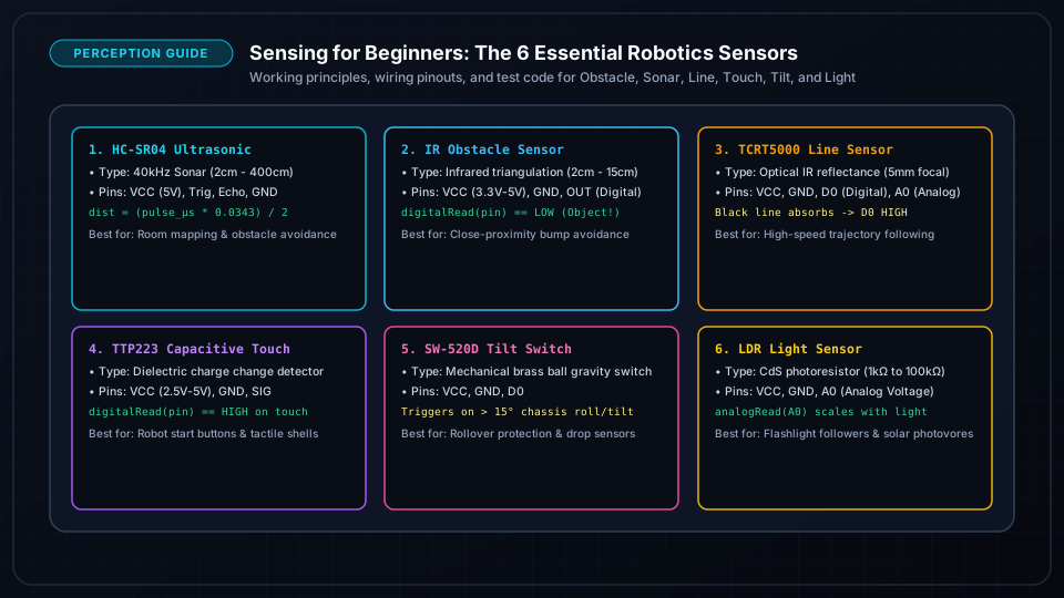
1. HC-SR04 Ultrasonic Distance Sensor
How It Works:
- 1The microcontroller sends a 10-microsecond HIGH pulse to the
TRIGpin. - 2The sensor emits eight 40 kHz sonic bursts.
- 3The
ECHOpin goes HIGH and stays HIGH until the sound reflects back off an object. - 4Formula:
Distance (cm) = (Echo Duration in microseconds * 0.0343) / 2
const int TRIG_PIN = 11;
const int ECHO_PIN = 12;

void setup() {
  pinMode(TRIG_PIN, OUTPUT);
  pinMode(ECHO_PIN, INPUT);
  Serial.begin(115200);
}

float getDistanceCm() {
  // Clear trigger
  digitalWrite(TRIG_PIN, LOW);
  delayMicroseconds(2);

  // Emit 10us pulse
  digitalWrite(TRIG_PIN, HIGH);
  delayMicroseconds(10);
  digitalWrite(TRIG_PIN, LOW);

  // Measure echo return time (timeout 30000us = ~5 meters)
  long duration = pulseIn(ECHO_PIN, HIGH, 30000);
  if (duration == 0) return 999.0; // No echo detected (clear path)

  return (duration * 0.0343) / 2.0;
}

void loop() {
  float dist = getDistanceCm();
  Serial.print("Front Distance: ");
  Serial.print(dist);
  Serial.println(" cm");
  delay(100);
}
2. Active Infrared (IR) Obstacle Sensor
How It Works:
An IR emitter LED shoots invisible 950nm light. If an obstacle is in front, light reflects into the IR receiver phototransistor. An onboard potentiometer adjusts sensitivity threshold:
- No Obstacle: Output pin is HIGH (5V).
- Obstacle Detected: Output pin drops to LOW (0V) and onboard indicator LED turns ON.
const int IR_OBSTACLE_PIN = 4;

void setup() {
  pinMode(IR_OBSTACLE_PIN, INPUT);
  Serial.begin(115200);
}

void loop() {
  if (digitalRead(IR_OBSTACLE_PIN) == LOW) {
    Serial.println("WARNING: Obstacle detected within 10cm!");
  }
  delay(50);
}
3. TCRT5000 Line & Surface Reflectance Sensor
Line Tracking Mechanics:
- White Background: Reflects strong IR light → Analog reading is LOW (< 200).
- Black Line: Absorbs IR light → Analog reading is HIGH (> 800).
const int LEFT_LINE_PIN = A1;
const int RIGHT_LINE_PIN = A2;
const int THRESHOLD = 500; // Calibrated midpoint value

void loop() {
  int leftVal = analogRead(LEFT_LINE_PIN);
  int rightVal = analogRead(RIGHT_LINE_PIN);

  if (leftVal > THRESHOLD && rightVal > THRESHOLD) {
    // Both on line -> Forward
  } else if (leftVal > THRESHOLD && rightVal <= THRESHOLD) {
    // Left on line, Right off -> Steer Left
  } else if (leftVal <= THRESHOLD && rightVal > THRESHOLD) {
    // Right on line, Left off -> Steer Right
  }
}
4. Capacitive Touch, SW-520D Tilt & LDR Light Sensors
Tilt / Tip-Over Safety Switch:
The SW-520D contains a tiny gold ball that closes internal contacts when upright. If the robot flips on its side or tips past 45°, the circuit opens immediately, triggering an emergency motor kill:
const int TILT_PIN = 3;

void setup() {
  pinMode(TILT_PIN, INPUT_PULLUP);
}

void loop() {
  if (digitalRead(TILT_PIN) == HIGH) {
    // Robot has tilted/flipped over!
    killAllMotors();
    Serial.println("EMERGENCY: Robot inverted!");
  }
}
Noise Filtering & Calibration Best Practices
Real-world sensor data is inherently noisy. Use this 3-sample median filter to eliminate false spikes:
float getFilteredDistance() {
  float a = getDistanceCm();
  delay(10);
  float b = getDistanceCm();
  delay(10);
  float c = getDistanceCm();

  // Return median value of 3 samples
  if ((a <= b && b <= c) || (c <= b && b <= a)) return b;
  if ((b <= a && a <= c) || (c <= a && a <= b)) return a;
  return c;
}
Frequently Asked Questions
Why does my ultrasonic sensor fail against soft fabric or curtains?
Ultrasonic sound waves are absorbed by soft, fluffy materials like acoustic foam, curtains, and pet fur instead of bouncing back. In addition, angled smooth surfaces (like a wall at 45 degrees) reflect the sound away from the sensor like a mirror. Combine ultrasonic with close-range IR sensors for robust obstacle coverage.
How do I calibrate my line sensors under different room lighting?
Ambient sunlight contains intense infrared radiation that shifts sensor baselines. Always write a 3-second startup calibration routine during setup() that sweeps the robot across the track while recording minimum and maximum analog values, calculating an adaptive dynamic threshold.