Key Engineering Takeaways
- •Cardboard and foamcore are unbeatable for rapid 10-minute prototyping; laser-cut acrylic is great for flat plates; 3D printing (PLA/PETG) allows custom integrated sensor brackets.
- •Metric M3 machine screws (lengths: 6mm, 10mm, 15mm, 25mm) paired with nylon lock nuts (Nyloc) form the universal robotics assembly standard.
- •Nylon standoffs (male-to-female and female-to-female) prevent live circuit board traces from shorting out against conductive or vibrating chassis plates.
- •Center of Gravity (CG) should sit directly between the main drive wheels to maximize traction and avoid tipping during rapid acceleration.
- •Always implement cable strain relief using zip ties and spiral wrap; pulling on loose wires is the #1 cause of intermittent loose pin connections during robot runs.
- • Basic hand tool safety (screwdrivers, cutters)
- • M3 Screw & Standoff Assortment Kit
- • PH0 / PH1 Phillips Screwdrivers
- • Zip Ties (Cable Ties)
- • Chassis Plate Material
Chassis Materials: Cardboard vs Acrylic vs 3D Print vs Aluminum
The structural frame of your robot dictates its weight, durability, and ease of modification:
| Material | Cost | Tools Needed | Durability | Best Robotics Role |
|---|---|---|---|---|
| Cardboard / Foamcore | Free / $1 | Utility knife, hot glue | Low (Flexes under load) | Rapid concept prototyping & weekend test beds |
| Cast Acrylic (Perspex) | $5 - $10 | Laser cutter / hand saw | Moderate (Can crack on impact) | Standard commercial flat-plate rover kits |
| 3D Printed (PLA / PETG) | $2 - $5 plastic | 3D Printer (FDM) | High (Flexible geometry) | Custom brackets, sensor turrets & snap-fit clips |
| Extruded Aluminum (2020) | $15 - $30 | Hex keys, miter saw | Extreme (Rigid structural) | Heavy combat bots, robot arms & industrial AGVs |
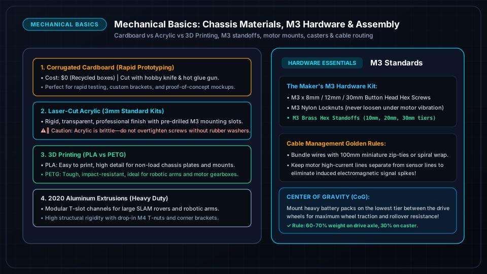
Standard Fasteners: Metric M2, M3 Screws & Standoffs
Never use mismatched wood screws or tape to secure sensitive electronics! Keep a standard metric fastener box on your bench:
Essential Fastener Types:
- M3 Button Head / Socket Head Screws:
- M3 x 6mm: Perfect for securing Arduino/ESP32 PCBs to standoffs.
- M3 x 10mm / 12mm: Connecting two acrylic chassis plates together.
- M3 x 30mm: Passing through TT yellow gearmotors for chassis clamping.
- Nylon Lock Nuts (Nyloc): Contain an internal nylon ring that grips screw threads tightly, preventing nuts from vibrating loose when DC motors run.
- Hexagonal Nylon Standoffs (M3 Female-Female & Male-Female): Elevate PCBs 10mm to 20mm above the chassis floor to protect pins from short circuits and route wires cleanly underneath.
Motor Mounting, Axles & Wheel Alignment
Securing Yellow TT Gearmotors:
- 1Use stamped aluminum L-brackets or 30mm pass-through M3 bolts with lock washers.
- 2Ensure both left and right motor drive shafts are perfectly perpendicular (90°) to the robot's centerline axis. If one motor is tilted even 3 degrees, the robot will experience continuous steering drift.
- 3Push wheels fully onto the flattened dual-D shaft until they seat firmly without rubbing against the motor gearbox casing.
Casters, CG (Center of Gravity) & Weight Distribution
The 3-Point Stability Rule for 2WD Rovers:
A 2-wheel drive rover relies on a third passive contact point—either a metal ball caster, a nylon omni-wheel, or a smooth skid pad.
         [ Front Left Wheel ] ────────── [ Front Right Wheel ]
                               ▲
                       [ Heavy Battery ]  <-- Center of Gravity (CG)
                               │
[ Passive Caster ]- Weight Distribution: Place the heaviest components (battery pack and motor driver) 60% to 70% directly over the drive axle.
- If too much weight is placed over the rear passive caster, the drive wheels lose friction and spin in place (wheel slip).
- If too much weight is in front of the drive wheels, the robot will nose-dive when braking.
Pro-Level Cable Management & Strain Relief
A tangle of loose wires ("rat's nest") causes 80% of intermittent hardware glitches when wires snag on wheels or vibrate loose:
- 1Strain Relief at Terminals: Always anchor wires with a small zip tie 2cm away from screw terminals so physical pulls do not yank copper out of the connector.
- 2Spiral Cable Wrap & Braided Sleeving: Bundle sensor ribbons and motor wires into neat harnesses.
- 3Color-Coded Wiring Convention:
- RED: VCC / Battery Positive (+)
- BLACK: GND / Ground (-)
- YELLOW / BLUE: Motor signals and PWM
- GREEN / WHITE: Sensor data and communication lines (SDA/SCL/Tx/Rx)
Frequently Asked Questions
What is the best 3D print filament for robotics parts?
PETG is the sweet spot for robotics chassis and brackets because it has higher impact resistance and heat tolerance than standard PLA, while being much easier to print than ABS or Nylon. PLA is fine for indoor, non-impact mounting plates.
Why does my ball caster get stuck on floor tile seams?
Small 10mm ball casters easily catch on rug edges and tile grout lines. Upgrade to a larger 19mm–25mm ball caster or a mini dual-roller omni-wheel for smoother omnidirectional rolling.