Key Engineering Takeaways
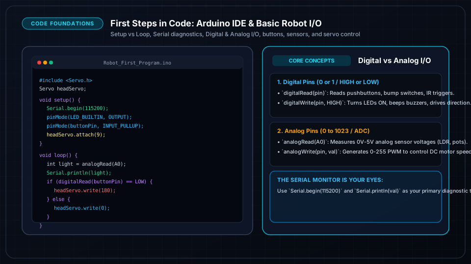
- •Arduino programs are composed of two mandatory functions: setup() (runs once on boot) and loop() (repeats infinitely).
- •pinMode(pin, mode) configures a GPIO pin as INPUT, OUTPUT, or INPUT_PULLUP (which enables an internal resistor for buttons).
- •digitalWrite() outputs either 0V or 5V, while analogRead() samples continuous voltages from 0 to 1023 (10-bit ADC).
- •PWM (Pulse Width Modulation) simulated analog output using analogWrite(pin, 0-255) to adjust motor speed or LED brightness.
- •The Serial Monitor at 115200 or 9600 baud is your #1 debugging tool to print real-time sensor numbers and error logs.
- • Computer with USB port or modern web browser
- • Arduino Uno or Nano
- • USB Cable
- • Breadboard + Jumper Wires
- • LED + 220Ω Resistor
- • Pushbutton
- • Potentiometer (10kΩ)
- • SG90 Micro Servo
Setting Up Arduino IDE & Wokwi Simulator
Before writing code, set up your development environment:
Option A: Install Arduino IDE 2.x
- 1Download Arduino IDE 2.x from the official Arduino website.
- 2Connect your Arduino board via USB.
- 3Select your board model under Tools → Board (e.g. Arduino Uno).
- 4Select the detected serial port under Tools → Port (e.g. COM3 on Windows or /dev/ttyUSB0 on Linux/Mac).
Option B: Zero-Install Instant Online Simulator (Wokwi)
If you don't have hardware in front of you, open [Wokwi.com](https://wokwi.com) in any modern browser. You can drag-and-drop Arduinos, ESP32s, sensors, LEDs, and servos and run real firmware with live interactive simulation.
Anatomy of an Arduino Sketch: setup() & loop()
Every robotics firmware file contains the fundamental skeleton:
// 1. GLOBAL SCOPE: Pin definitions, variables, and libraries
const int LED_PIN = 13;

void setup() {
  // 2. SETUP: Runs ONCE when power turns on or reset is pressed
  pinMode(LED_PIN, OUTPUT);
  Serial.begin(115200);
  Serial.println("Robot Controller Initialized!");
}

void loop() {
  // 3. MAIN LOOP: Repeats continuously as fast as possible
  digitalWrite(LED_PIN, HIGH); // Turn LED ON (5V)
  delay(500);                  // Wait 500 milliseconds
  digitalWrite(LED_PIN, LOW);  // Turn LED OFF (0V)
  delay(500);                  // Wait 500 milliseconds
}Analog I/O: ADC Inputs & PWM Output
Reading Continuous Analog Voltages:
Analog sensors (like light-dependent resistors or potentiometers) output continuous voltages from 0V to 5V. The built-in Analog-to-Digital Converter (ADC) converts this into a number from 0 to 1023:
const int POT_PIN = A0;  // Center pin of 10k potentiometer
const int MOTOR_PWM = 9; // PWM pin on Arduino Uno (~9)

void setup() {
  pinMode(MOTOR_PWM, OUTPUT);
  Serial.begin(115200);
}

void loop() {
  int sensorValue = analogRead(POT_PIN); // Reads 0 to 1023

  // Map 10-bit input (0-1023) to 8-bit PWM speed (0-255)
  int speed = map(sensorValue, 0, 1023, 0, 255);

  analogWrite(MOTOR_PWM, speed); // Generates PWM signal for motor driver

  Serial.print("Raw Sensor: ");
  Serial.print(sensorValue);
  Serial.print(" -> Calculated Speed: ");
  Serial.println(speed);
  delay(50);
}
Serial Debugging: The Robot Diagnostic Window
When your robot doesn't behave as expected, never guess—print variables to the Serial Monitor!
- 1Open Tools → Serial Monitor in Arduino IDE.
- 2Set the baud rate dropdown to match your code (
115200or9600). - 3Use formatted debugging prints:
Serial.print("Distance: ");
Serial.print(distanceCm);
Serial.print(" cm | State: ");
Serial.println(robotState);
Installing Libraries & Driving an RC Servo
Arduino libraries provide pre-written drivers for complex hardware. The standard <Servo.h> library generates precise 50Hz PWM timing (1.0ms to 2.0ms pulses) to hold angles between 0° and 180°:
#include <Servo.h>

Servo scanRadar; // Create servo object to control ultrasonic sensor turret

void setup() {
  scanRadar.attach(9); // Connect SG90 signal wire (orange/yellow) to Pin 9
}

void loop() {
  // Sweep from 0 degrees to 180 degrees
  for (int angle = 0; angle <= 180; angle += 15) {
    scanRadar.write(angle);
    delay(100);
  }

  // Sweep back from 180 degrees to 0 degrees
  for (int angle = 180; angle >= 0; angle -= 15) {
    scanRadar.write(angle);
    delay(100);
  }
}
Frequently Asked Questions
Why do I get gibberish characters in the Serial Monitor?
This happens when the baud rate selected in the bottom-right corner of the Serial Monitor window does not match the baud rate specified in your Serial.begin(baud) command. If your code says Serial.begin(115200);, ensure the Serial Monitor is set to 115200 baud.
Why does my servo jitter and cause the Arduino to disconnect?
Even small SG90 servos can draw 500mA+ when moving or under mechanical load. If powered directly from the Arduino 5V pin, this voltage drops sharply, resetting the USB communication. Power the servo VCC wire directly from an external battery pack or 5V regulator, keeping all GND wires tied together.