Pure Analog Light-Follower
Construct a no-code, microcontroller-free phototactic robot that seeks flashlights using dual LDR light sensors and 2N2222 transistor amplifier bridges.
Explore the foundations of autonomous robotics inspired by Valentino Braitenberg! This classic "Braitenberg Vehicle 2a" uses zero software and zero microcontrollers: two Light Dependent Resistors (LDRs) cross-coupled to two 2N2222 NPN transistors drive left and right DC gear motors, creating natural phototactic (light-seeking) steering behavior.
Bill of Materials (BOM) & Hardware Components
| Component | Specifications | Qty | Approx Cost |
|---|---|---|---|
| 2N2222 / BC547 NPN Transistors | General purpose NPN silicon current amplifiers (TO-92 package) | 2 | $1.00 |
| LDR Photoresistors (5mm GL5528) | Light-dependent variable resistors (1kΩ bright, 100kΩ dark) | 2 | $1.20 |
| 1 kΩ Resistors (1/4 Watt) | Pull-down voltage divider bias resistors | 2 | $0.40 |
| Mini TT DC Gearmotors with Wheels (3V-6V) | Dual shaft yellow gearboxes with rubber high-traction tires | 2 | $4.50 |
| Half-Size Solderless Breadboard & Jumpers | 400-tie point breadboard acting as the structural chassis base | 1 | $2.50 |
| 4xAA / 4xAAA Battery Holder (4.8V - 6V) | Direct power source with ON/OFF switch | 1 | $1.50 |
Electrical & System Architecture
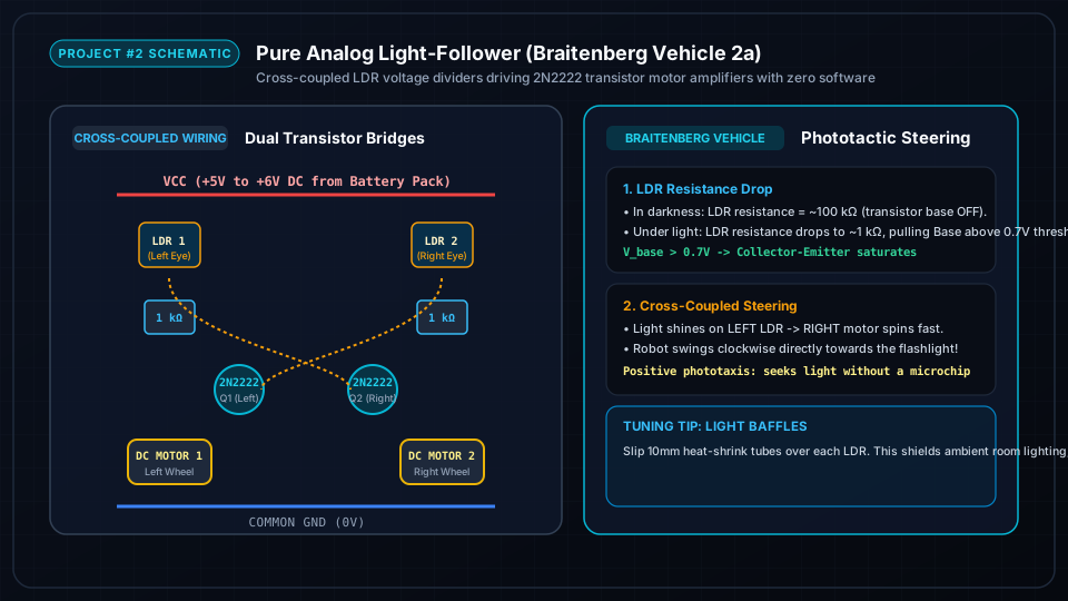
A cross-coupled analog Braitenberg circuit: The Left LDR photoresistor forms a voltage divider with a 1kΩ resistor feeding the Base of the RIGHT motor transistor. The Right LDR divider feeds the LEFT motor transistor. When light strikes the left sensor, the right wheel accelerates, steering the chassis toward the light beam!
Step-by-Step Assembly & Configuration Tutorial
Follow each milestone step with photos, wiring checks, and testing procedures.
Breadboard Layout & Transistor Switching Circuit
Insert the two 2N2222 NPN transistors into the half-size breadboard. Wire their Emitters directly to the negative GND power rail, and connect 1kΩ pull-down resistors from the Base pins to GND.
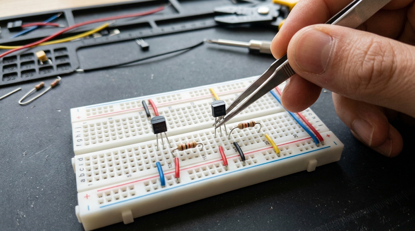
- Orient the 2N2222 transistors with the flat face pointing forward: Left pin is Emitter, Center is Base, Right is Collector.
- Connect Left Emitter and Right Emitter to the blue negative (-) GND power rail.
- Insert 1kΩ resistors between Base and GND to ensure transistors remain fully OFF in darkness.
Wiring Dual LDR Sensors & Cross-Coupled Base Drivers
Mount the two LDR photoresistors at the front corners of the breadboard angled outward at 30°. Connect each LDR from the +5V power rail across to the opposite motor transistor Base.
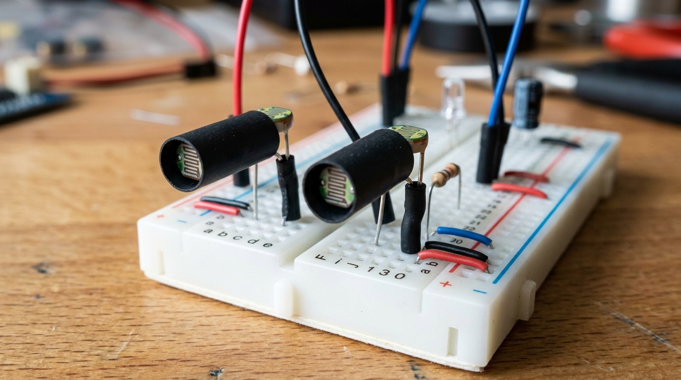
- Wire Left LDR from +VCC to the Base of the Right motor transistor.
- Wire Right LDR from +VCC to the Base of the Left motor transistor.
- Slip 10mm pieces of black heat-shrink tubing over both LDR barrels to act as directional light baffles.
- Connect the positive leads of both DC gear motors to +VCC, and negative motor leads to the Transistor Collectors.
Chassis Assembly & Flashlight Pursuit Testing
Attach the two yellow TT gearmotors directly to the sides of the breadboard with double-sided foam tape. Connect the 4xAA battery pack and test the robot on the floor.
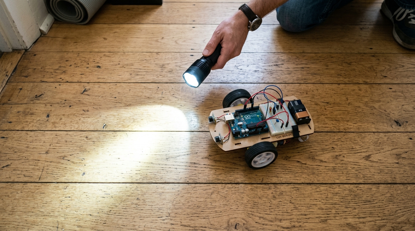
- Attach a small ball caster or smooth plastic slider glide under the rear of the breadboard for 3-point balance.
- Power on the battery pack in a dimly lit room: the robot should remain stationary.
- Shine a bright flashlight ahead of the robot: watch both wheels engage.
- Move the flashlight beam left and right: the robot smoothly follows the beam around obstacles!