2WD Smart Rover (Arduino / ESP32)
Construct an essential 2-wheel drive autonomous rover featuring dual TT gearmotors, an L298N / L9110S motor driver, and Arduino/ESP32 differential drive kinematics.
The foundational benchmark platform for mobile robotics! This project teaches mechanical chassis assembly, dual H-bridge motor driver interfacing, PWM speed modulation, and differential drive steering kinematics (forward, reverse, spin turns, and curve arcs) in C++ firmware.
Bill of Materials (BOM) & Hardware Components
| Component | Specifications | Qty | Approx Cost |
|---|---|---|---|
| Arduino Uno / Nano or ESP32 DevKit | Microcontroller for closed-loop motion kinematics and PWM generation | 1 | $5.50 |
| 2WD Robot Chassis Kit | Laser-cut acrylic plate, 2x TT yellow gearmotors, 2 wheels, 1 ball caster | 1 | $9.00 |
| L298N or L9110S Dual H-Bridge Motor Driver | 2A dual-channel H-Bridge driving left and right DC gearmotors | 1 | $3.50 |
| 2S 7.4V 18650 Li-ion Battery Holder with Switch | High-current rechargeable power supply for motors and MCU | 1 | $4.00 |
| DuPont Jumper Wires & M3 Hardware Kit | Male-to-Female and Male-to-Male jumper cables with brass standoffs | 1 | $2.00 |
Electrical & System Architecture
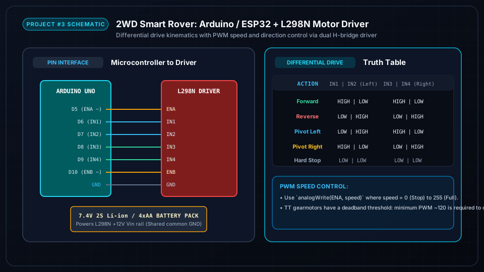
Arduino digital PWM pins D5 and D10 connect to L298N ENA and ENB speed pins; D6, D7, D8, D9 connect to IN1, IN2, IN3, IN4 direction logic. The 7.4V battery pack feeds the L298N +12V power input, and the driver 5V regulator powers the Arduino with a shared common ground.
Step-by-Step Assembly & Configuration Tutorial
Follow each milestone step with photos, wiring checks, and testing procedures.
Assembling 2WD Chassis, Gearmotors & Caster Wheel
Mount the two yellow TT DC gear motors onto the acrylic base plate using the included aluminum brackets and M3 bolts. Press on the rubber drive wheels and bolt the front swivel caster.
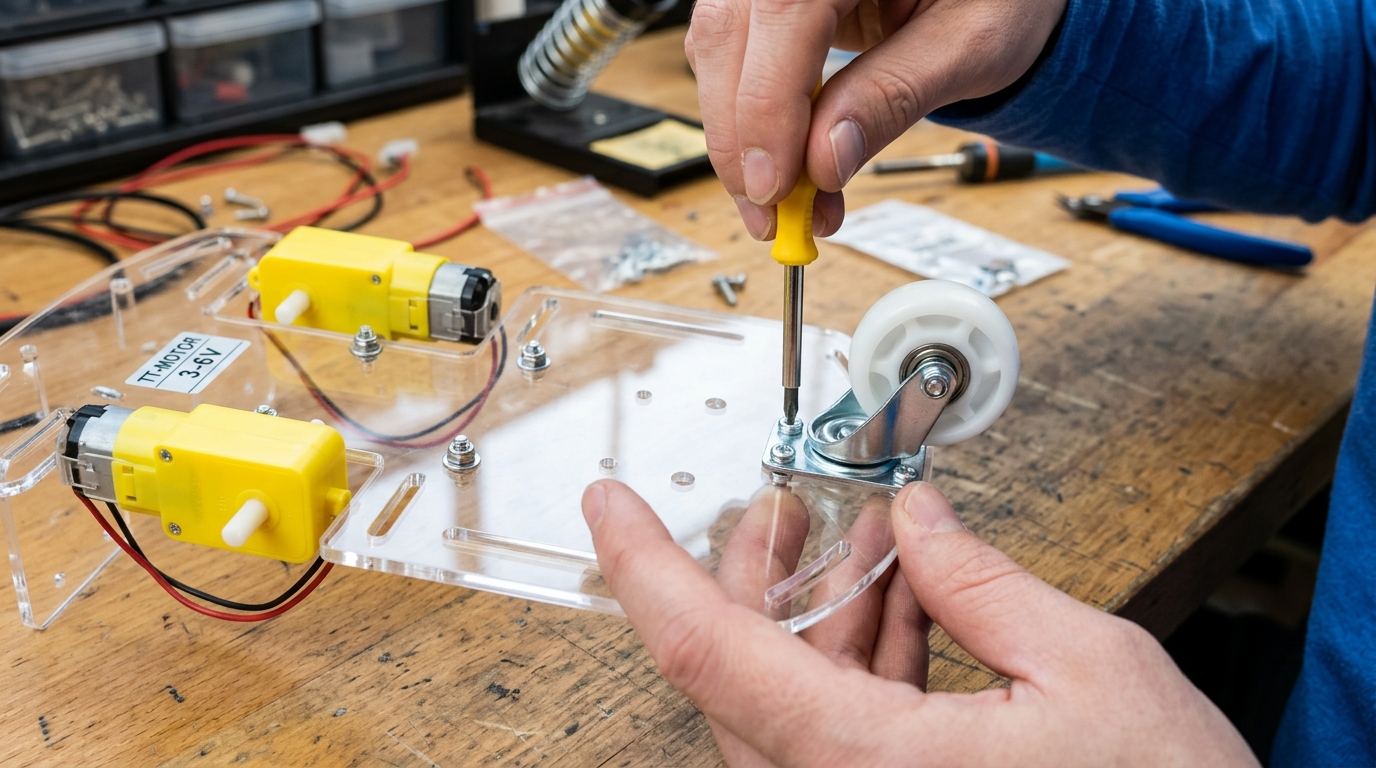
- Peel off the protective paper film from the transparent acrylic base plate.
- Attach motor mounting brackets with M3x30mm screws and locknuts.
- Solder red and black 22AWG stranded wires to each motor terminal (add 0.1µF ceramic capacitors across terminals to eliminate electrical noise).
- Fasten the front omni-directional swivel ball caster using 4x M3 standoffs to ensure level ground clearance.
Wiring L298N Motor Driver to Arduino & Battery Pack
Mount the L298N motor driver and Arduino Uno on top of the chassis. Wire the motor terminals, logic inputs, and battery power supply.
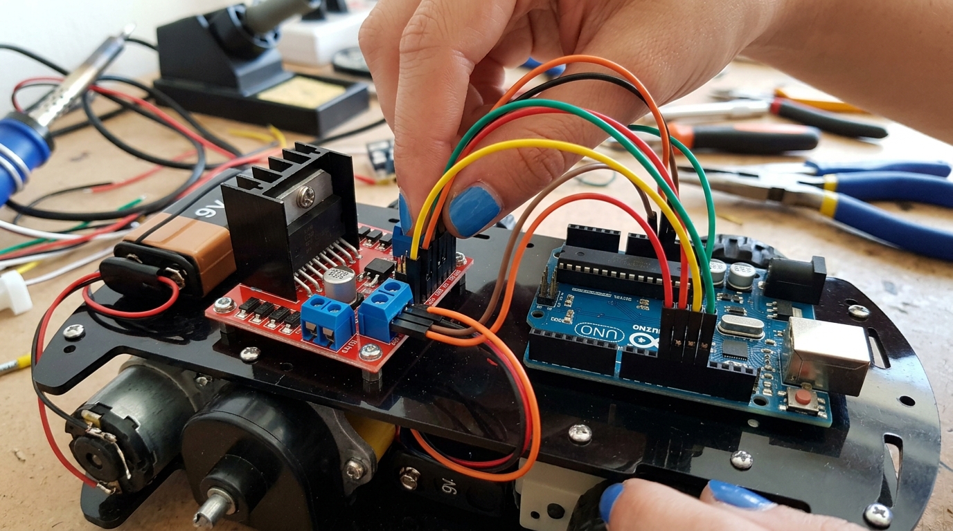
- Connect Left Motor to L298N OUT1/OUT2 screw terminals; Right Motor to OUT3/OUT4.
- Connect Arduino Pins: ENA -> D5, IN1 -> D6, IN2 -> D7, IN3 -> D8, IN4 -> D9, ENB -> D10.
- Connect positive battery lead to L298N +12V input, and negative lead to L298N GND.
- Run a jumper wire from L298N GND to Arduino GND (Common Ground Reference).
- Connect L298N +5V output to Arduino 5V pin to power the microcontroller from the main battery.
Programming Differential Drive Motion Kinematics
Upload the motion control sketch to the Arduino. Test fundamental movement routines: Forward, Reverse, Spin Left, Spin Right, and Variable Speed Arcs.
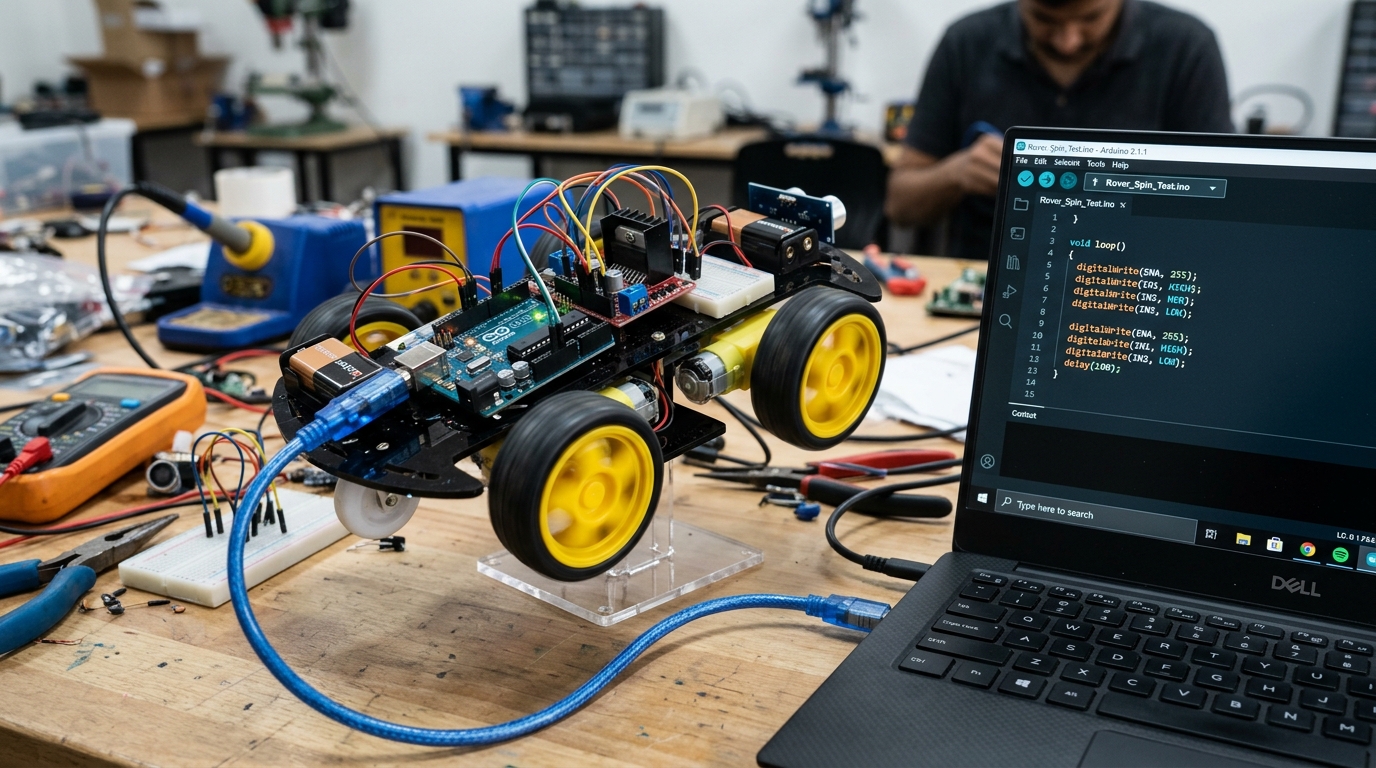
- Open the Arduino IDE and create helper functions: `driveForward()`, `driveReverse()`, `spinLeft()`, `spinRight()`, and `stopMotors()`.
- Verify motor rotation directions: if the left motor spins in reverse during `driveForward()`, swap the IN1 and IN2 pins in code.
- Implement PWM speed calibration: tune Left and Right speeds to compensate for minor motor manufacturing variations.
- Run an autonomous figure-8 driving sequence on the floor!