Key Engineering Takeaways
- •Never change multiple variables at once; isolate software, logic wiring, and power distribution systematically.
- •Upload errors are usually caused by missing CH340 USB drivers, faulty USB charge-only cables, or hardware connected to Arduino Pins 0 & 1 (Rx/Tx).
- •Brownout resets happen when high motor inrush current drops battery voltage below the MCU reset threshold; fix with 18650 Li-ion batteries and bulk capacitors.
- •Robots spinning in circles indicate flipped motor polarity (+/-) or uneven mechanical friction between left and right gearboxes.
- •A digital multimeter with a continuity beeper and DC voltage mode is your most powerful troubleshooting tool.
- • Basic familiarity with multimeter voltage & continuity testing
- • Digital Multimeter
- • USB Cable (Data Capable)
- • Extra 100uF - 470uF Electrolytic Capacitors
The Scientific Robotics Debugging Methodology
When a robot fails to work, beginners often guess randomly or rewrite their code in frustration. Instead, apply the Isolate & Conquer method:
         [ 1. Power Verification ]  ──> Check battery voltage under load (> 7.0V)
                    │
         [ 2. Logic Verification ]  ──> Verify MCU boots and prints over Serial
                    │
         [ 3. Signal Continuity ]   ──> Beep test jumper wires (0.00 ohms)
                    │
         [ 4. Motor Direct Drive ]  ──> Test motor directly across battery terminals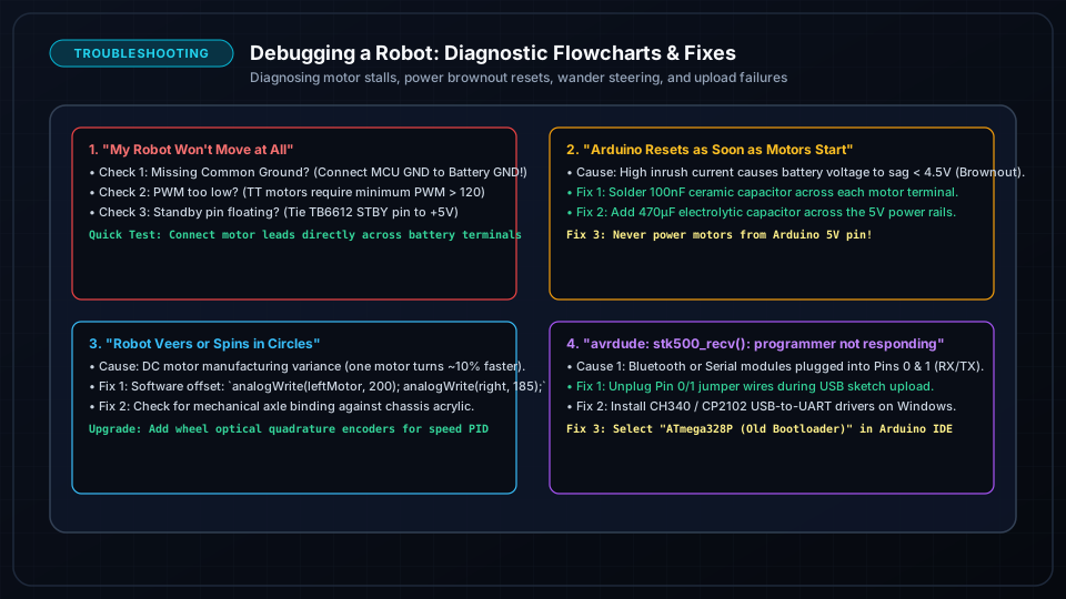
Problem 1: Sketch Upload Errors & Port Not Found
Error: `avrdude: stk500_recv(): programmer is not responding` or `Port not detected`
Root Cause 1: "Charge-Only" USB Cable
Many cheap USB cables supplied with phones contain only 2 power wires (+5V, GND) and lack the internal D+ and D- data wires.
- Fix: Swap to a known high-quality micro-USB or USB-C data cable.
Root Cause 2: Missing CH340 / CP2102 USB Drivers
Budget Arduino Nano and ESP32 clone boards use the CH340 or CP2102 USB-to-UART bridge chip instead of the expensive FTDI chip.
- Fix: Download and install the official WCH CH340/CH341 USB Driver for Windows/Mac.
Root Cause 3: Devices Connected to Pins 0 and 1 (RX / TX)
Digital Pins 0 and 1 on the Arduino Uno/Nano are physically shared with the onboard USB hardware. If a Bluetooth module (HC-05) or sensor is plugged into Pins 0 or 1 during upload, it corrupts the firmware flash process.
- Fix: Disconnect wires from Pins 0 and 1 while uploading code, then plug them back in.
Problem 2: Robot Resets Every Time Motors Start (Brownout)
Symptom:
The robot boots up, displays text on the screen or blinks an LED, but the exact microsecond the wheels attempt to spin, the microcontroller resets, restarts, and enters an infinite reboot loop.
The Physics:
When a stationary DC motor turns on, its internal coils have zero back-EMF, causing it to draw peak stall current (1.5A to 3.0A) for 20ms to 50ms. Weak batteries (such as 9V rectangular PP3 batteries) have high internal resistance; their voltage instantaneously plunges from 9V down to 3V, triggering the microcontroller's internal Brownout Detector (BOD).
The 3-Step Permanent Solution:
- 1Throw away 9V rectangular batteries: Upgrade to two 18650 Li-ion cells in series (7.4V nominal) or a 6x AA NiMH pack.
- 2Add a Bulk Decoupling Capacitor: Solder a 470uF or 1000uF electrolytic capacitor (rated for 16V or 25V) directly across the motor driver's
VMSandGNDpower input terminals (observing polarity: stripe = negative). - 3Separate Power Feeds: Run separate thick power wires from the battery connector directly to the motor driver, and another wire through a 5V buck converter to the MCU.
Problem 3: Robot Veers or Spins in Circles Instead of Driving Straight
Diagnostic Checklist:
- 1Flipped Motor Polarity: If the robot spins in place when commanded forward, one motor is wired in reverse. Swap the two motor wire leads in the driver output screw terminal.
- 2Missing PWM Deadband: If one wheel starts spinning at PWM = 80 while the other doesn't move until PWM = 120, the gearbox has tighter gear teeth mesh. Add a minimum starting PWM offset in software.
- 3Wheel Rubbing: Check if the plastic wheel hub is physically scraping against the chassis wall or motor casing.
Problem 4: Phantom Obstacles & Glitchy Sensor Readings
Diagnostic Checklist:
- Ultrasonic Reading 0 cm or 999 cm: Verify you are providing at least 10 microseconds on the
TRIGpulse. Check that the sensor has a minimum 60ms delay between consecutive pings to allow old acoustic echoes to dissipate. - IR Sensors Always Triggered: Ambient sunlight or incandescent room lamps flood the phototransistor. Turn the onboard 10k trim potentiometer counter-clockwise until the indicator LED turns off.
Quick Bench Diagnostic Flowchart
| Symptom | Primary Check | Quick Action |
|---|---|---|
| No LEDs turn on | Battery voltage | Test battery with multimeter; verify power switch continuity |
| MCU warm to the touch | Short circuit / Overvoltage | Unplug immediately; check for 5V applied to 3.3V GPIO |
| Motors hum but don't spin | Driver enable jumper | Ensure ENA and ENB jumpers are installed or PWM > 90 |
| Servos twitch wildly | Shared GND missing | Connect battery negative to Arduino GND |
Frequently Asked Questions
How do I know if my Arduino microcontroller is permanently fried?
Unplug all external wires and shields, and connect the bare Arduino board to your computer via USB. If the "ON" LED does not light up, the main ATmega chip becomes scorching hot within 5 seconds, or the computer shows "USB Device Drawing Too Much Power / Malfunctioned", the board has suffered irreversible hardware damage.
Can I use a multimeter to measure PWM duty cycle?
Standard multimeters in DC voltage mode will display the time-averaged voltage (e.g. 50% PWM at 5V displays ~2.5V DC). For true pulse frequency and duty cycle waveform visualization, use a multimeter with Hz/% duty cycle mode or an entry-level USB logic analyzer.