2-DOF Desktop Robot Arm / Gripper
Construct a desktop articulated robot arm with laser-cut / 3D-printed links, dual SG90 servos, potentiometer analog joint mapping, and pick-and-place gripper.
Master kinematic linkages and multi-servo coordination! This 2-DOF desktop robotic manipulator features a rotating turntable base (Yaw), an articulated shoulder pitch link, and a mechanical claw gripper powered by 3 SG90/MG90S servos. Includes manual potentiometer joystick mapping and programmable automated pick-and-place routines.
Bill of Materials (BOM) & Hardware Components
| Component | Specifications | Qty | Approx Cost |
|---|---|---|---|
| SG90 9g (or metal-gear MG90S) Micro Servos | 1.8 - 2.2 kg.cm torque, 0°-180° rotation with horns and screws | 3 | $7.50 |
| 2-DOF Acrylic / 3D-Printed Arm Frame & Gripper Kit | Base turntable, bicep arm link, and gear-driven claw gripper | 1 | $8.50 |
| 10 kΩ Rotary Potentiometer Modules | Analog voltage dividers for intuitive real-time joint control | 2 | $2.00 |
| Arduino Uno / Nano Microcontroller | Reads analog voltages (A0-A1) and outputs 50Hz PWM servo pulses | 1 | $5.50 |
| 5V 2.5A Dedicated External Power Adapter | Isolated servo power supply preventing microcontroller brownouts | 1 | $5.00 |
Electrical & System Architecture
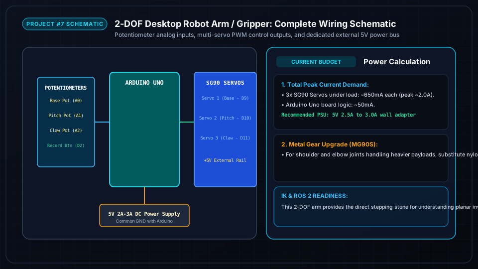
Potentiometer 1 (Base Yaw) connects to Arduino Analog A0; Potentiometer 2 (Shoulder Pitch) connects to A1. Servo control lines connect to PWM pins D9, D10, D11. Servo positive power leads are fed directly from an external 5V 2.5A supply with common ground.
Step-by-Step Assembly & Configuration Tutorial
Follow each milestone step with photos, wiring checks, and testing procedures.
Assembling Turntable Base, Arm Linkages & Gripper Claw
Zero all 3 servos to 90° before mechanical fastening. Assemble the rotating base turntable (Servo 1), shoulder elevation pivot (Servo 2), and geared gripper claw (Servo 3).
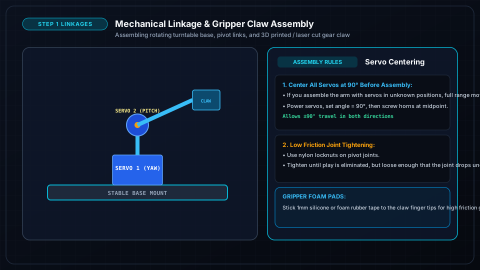
- Power all servos with a 90° center sketch before screwing horns into the acrylic/3D-printed linkages.
- Assemble the base rotating turntable plate with M3 pivot screws and nylon locknuts.
- Attach the shoulder linkage arm to the base servo horn.
- Assemble the claw gripper gears: verify the jaws open and close smoothly across a 0° to 90° span without binding.
Wiring Potentiometers, Servos & External 5V Power Rail
Wire the two 10kΩ potentiometers to Arduino analog inputs A0 and A1. Connect all 3 servo power lines to a dedicated external 5V 2.5A power adapter sharing common ground.
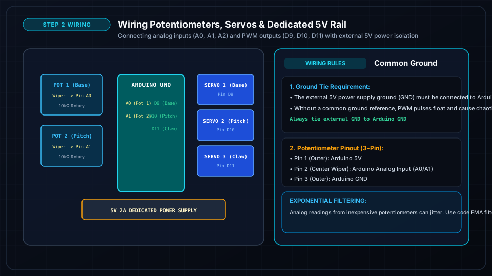
- Connect Potentiometer 1 Wiper -> Pin A0; Potentiometer 2 Wiper -> Pin A1.
- Connect Servo PWM Signal Pins: Base -> D9, Shoulder -> D10, Gripper Claw -> D11.
- Connect external 5V power supply (+) directly to all 3 servo red power leads.
- Tie external power supply GND and Arduino GND together to establish a shared ground reference.
Programming Joint Angle Mapping & Pick-and-Place Automation
Upload the firmware sketch: map raw 0-1023 analog ADC voltages to 10°-170° servo angles, add exponential smoothing filters, and program automated pick-and-place cycles.
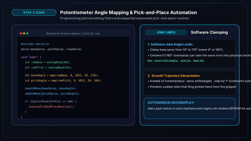
- Map analog inputs: `baseAngle = map(analogRead(A0), 0, 1023, 10, 170);`.
- Implement software joint limit clamping to prevent servos from hitting physical mechanical stops.
- Add exponential moving average (EMA) smoothing to eliminate potentiometer electrical jitter.
- Program an automated sequence to grasp a foam cube, lift it, rotate 90°, and deposit it into a target container!